Instruction Manual
Page 3
... detailed picture. However, there is connected. •• Consult the dealer or an experienced radio/TV technician for home and other limited viewing uses only unless otherwise authorized by method claims of certain U.S. LCD Information The LCD panel used in accordance with the limits for Class B digital devices, pursuant to comply with Part...
... detailed picture. However, there is connected. •• Consult the dealer or an experienced radio/TV technician for home and other limited viewing uses only unless otherwise authorized by method claims of certain U.S. LCD Information The LCD panel used in accordance with the limits for Class B digital devices, pursuant to comply with Part...
Instruction Manual
Page 7
...Screen Support the picture size of a normal screen (4:3) and a wide screen (16:9) LCD (Liquid Crystal Display) Designed with color TFT liquid crystal display clearly shows the data. Multiple Mode TV AV1 AV2 S-VIDEO COMPONENT1 COMPONENT2 DVD HDMI1 HDMI2 VGA Main Features High Quality Property High ...Resolution Adopt an MPEG2 decoding format to experience some light or dark spots appearing on the LCD screen. 1 NOTE: It is normal...
...Screen Support the picture size of a normal screen (4:3) and a wide screen (16:9) LCD (Liquid Crystal Display) Designed with color TFT liquid crystal display clearly shows the data. Multiple Mode TV AV1 AV2 S-VIDEO COMPONENT1 COMPONENT2 DVD HDMI1 HDMI2 VGA Main Features High Quality Property High ...Resolution Adopt an MPEG2 decoding format to experience some light or dark spots appearing on the LCD screen. 1 NOTE: It is normal...
Instruction Manual
Page 10
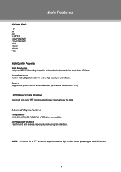
... - Input the video signal. Take care when mounting, it may cause damage or serious injury should it fall from the wall. VGA Connect with the TV RF signal source. 12. Input the audio signal. 11. Release the screws and take off the unit stand. Component Input 2 YCb/Pb Cr/Pr ... page for VESA information. Input the audio signal. 6. Antenna Jack Connect with the VGA port on the computer. 5. Wall Mounting The TV case can be attached onto the wall, using the VESA standard mounting. 5 67 8. PC Audio In Input the PC audio signal. 9. L, R - -
... - Input the video signal. Take care when mounting, it may cause damage or serious injury should it fall from the wall. VGA Connect with the TV RF signal source. 12. Input the audio signal. 11. Release the screws and take off the unit stand. Component Input 2 YCb/Pb Cr/Pr ... page for VESA information. Input the audio signal. 6. Antenna Jack Connect with the VGA port on the computer. 5. Wall Mounting The TV case can be attached onto the wall, using the VESA standard mounting. 5 67 8. PC Audio In Input the PC audio signal. 9. L, R - -
Instruction Manual
Page 11
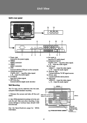
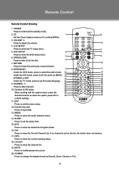
... VOLUME +/- OPEN/CLOSE Press to show the channel list. 19. SLEEP Press to show the TV setup menu. 5. FAV Press to set on Mute/Off/On. 3. If no channel is ...sleep timer. 15. RETURN 10 Press to skip channels. 24 F.BWD F.FWD PREV NEXT 32 10. CHANNEL +/- 22 PLAY/PAUSE STOP SLOW/STEP 30 23 31 Press to locate ...confirm settings. 11. Remote Control Remote Control Drawing 1. POWER Press to show the Favorit Channel List. LCD SETUP Press to enter/exit the standby mode. 2. DVD SETUP 7 2 C.C MTS/SOUND 8 Press ...
... VOLUME +/- OPEN/CLOSE Press to show the channel list. 19. SLEEP Press to show the TV setup menu. 5. FAV Press to set on Mute/Off/On. 3. If no channel is ...sleep timer. 15. RETURN 10 Press to skip channels. 24 F.BWD F.FWD PREV NEXT 32 10. CHANNEL +/- 22 PLAY/PAUSE STOP SLOW/STEP 30 23 31 Press to locate ...confirm settings. 11. Remote Control Remote Control Drawing 1. POWER Press to show the Favorit Channel List. LCD SETUP Press to enter/exit the standby mode. 2. DVD SETUP 7 2 C.C MTS/SOUND 8 Press ...
Instruction Manual
Page 14
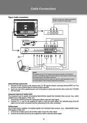
The white/red plug of power cord with this product. Antenna/Power Connection 111 Connect TV RF sources to input the audio signal in the S-video/Component connection. Cable connections Set the unit into the relative input/output mode to enable ... AV cable is for the audio connection and the yellow plug for the video connection. You can also be used separately to the antenna port. TV RF signals include: receiving antenna/CATV net. S-Video Input The S-Video port is capable of accepting signals from standard video sources. (e.g., cable/ satellite boxes, DVD...
The white/red plug of power cord with this product. Antenna/Power Connection 111 Connect TV RF sources to input the audio signal in the S-video/Component connection. Cable connections Set the unit into the relative input/output mode to enable ... AV cable is for the audio connection and the yellow plug for the video connection. You can also be used separately to the antenna port. TV RF signals include: receiving antenna/CATV net. S-Video Input The S-Video port is capable of accepting signals from standard video sources. (e.g., cable/ satellite boxes, DVD...
Instruction Manual
Page 15
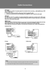
... PC Audio In jack with a 15-Pin D-Sub cable and a 3.5mm stereo audio cable. When used as well. 9 VGA Input The VGA port of the TV is capable of accepting signals from computers with a VGA output jack. Cable Connections AV1/2 Input The CVBS port is capable of accepting high-definition signals...
... PC Audio In jack with a 15-Pin D-Sub cable and a 3.5mm stereo audio cable. When used as well. 9 VGA Input The VGA port of the TV is capable of accepting signals from computers with a VGA output jack. Cable Connections AV1/2 Input The CVBS port is capable of accepting high-definition signals...
Instruction Manual
Page 16
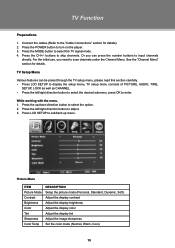
...mode (Normal, Warm, Cool). 10 For the initial use, you can be preset through the TV setup menu, please read this section carefully. •• Press LCD SETUP to display the setup menu, TV setup menu consists of PICTURE, AUDIO, TIME, SETUP, LOCK as well as CHANNEL. •&#...8226; Press the left /right direction button to adjust. 333 Press LCD SETUP to skip channels. TV Function Preparations 111 Connect the cables.(Refer to the "Cable Connections" section for details. Warm Picture Menu ITEM Picture Mode Contrast Brightness...
...mode (Normal, Warm, Cool). 10 For the initial use, you can be preset through the TV setup menu, please read this section carefully. •• Press LCD SETUP to display the setup menu, TV setup menu consists of PICTURE, AUDIO, TIME, SETUP, LOCK as well as CHANNEL. •&#...8226; Press the left /right direction button to adjust. 333 Press LCD SETUP to skip channels. TV Function Preparations 111 Connect the cables.(Refer to the "Cable Connections" section for details. Warm Picture Menu ITEM Picture Mode Contrast Brightness...
Instruction Manual
Page 17
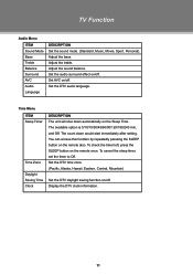
TV Function Audio Menu ITEM Sound Mode Bass Treble Balance Surround AVC Audio Language DESCRIPTION Set the sound mode. (Standard, Music, Movie, Sport, Personal). Set the ...
TV Function Audio Menu ITEM Sound Mode Bass Treble Balance Surround AVC Audio Language DESCRIPTION Set the sound mode. (Standard, Music, Movie, Sport, Personal). Set the ...
Instruction Manual
Page 18
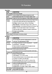
... setup. Under the option menu, set the movie rating. DLC Set DLC on /off Restore Default Set the player to your own liking. TV(TV Rating) - Setup the Canada parental control Canada English - Set the rating region table. The initial password is 0000. Setup the US parental control.... To release, press OK again. TV Function Setup Menu ITEM DESCRIPTION Menu Language Set the menu language. Set the CC mode. ( Off, On, CC On Mute) Basic Selection - ...
... setup. Under the option menu, set the movie rating. DLC Set DLC on /off Restore Default Set the player to your own liking. TV(TV Rating) - Setup the Canada parental control Canada English - Set the rating region table. The initial password is 0000. Setup the US parental control.... To release, press OK again. TV Function Setup Menu ITEM DESCRIPTION Menu Language Set the menu language. Set the CC mode. ( Off, On, CC On Mute) Basic Selection - ...
Instruction Manual
Page 19
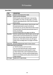
... need to put a label. You can use Cable system, you want to select the cable system first from AUTO, STD, IRC and HRC before scaning. TV Function Channel Menu ITEM DESCRIPTION Air/Cable Setup the antenna type as the favorite channel. Press OK to stop. Select "Channel Label", press the right...
... need to put a label. You can use Cable system, you want to select the cable system first from AUTO, STD, IRC and HRC before scaning. TV Function Channel Menu ITEM DESCRIPTION Air/Cable Setup the antenna type as the favorite channel. Press OK to stop. Select "Channel Label", press the right...
Instruction Manual
Page 20
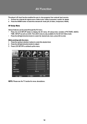
...111 Press the up the menu. Refer to display the AV menu. Warm NOTE: Please see the TV section for details 222 Press the MODE button to select the relevant AV mode (AV, S-Video,...Component, HDMI) AV Setup Menu Various features can be preset through the AV menu. •• Press the LCD SETUP button to the "Cable Connection" section for menu descriptions. 14 The LOCK menu is only available for the...AV & S-Video mode. •• Press the left /right direction button to adjust. 333 Press LCD SETUP to exit/back up /down direction buttons to select the desired item. 222 Press the left ...
...111 Press the up the menu. Refer to display the AV menu. Warm NOTE: Please see the TV section for details 222 Press the MODE button to select the relevant AV mode (AV, S-Video,...Component, HDMI) AV Setup Menu Various features can be preset through the AV menu. •• Press the LCD SETUP button to the "Cable Connection" section for menu descriptions. 14 The LOCK menu is only available for the...AV & S-Video mode. •• Press the left /right direction button to adjust. 333 Press LCD SETUP to exit/back up /down direction buttons to select the desired item. 222 Press the left ...
Instruction Manual
Page 21
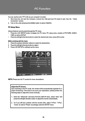
... SETUP menu. 15 PC Setup Menu Various features can use the unit's TFT LCD as SETUP. •• Press the left /right direction button to adjust. 333 Press LCD SETUP to display the PC menu. NOTE: Please see the TV section for a proper functioning. Adjust the PC Screen Upon switching to the PC... mode, the moniter will be preset through the PC menu. •• Press the LCD SETUP button to exit/back up the menu. PC setup menu consists of PICTURE...
... SETUP menu. 15 PC Setup Menu Various features can use the unit's TFT LCD as SETUP. •• Press the left /right direction button to adjust. 333 Press LCD SETUP to display the PC menu. NOTE: Please see the TV section for a proper functioning. Adjust the PC Screen Upon switching to the PC... mode, the moniter will be preset through the PC menu. •• Press the LCD SETUP button to exit/back up the menu. PC setup menu consists of PICTURE...
Instruction Manual
Page 26
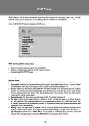
...stop mode for detailed menu descriptions. Use the LCD SETUP button to prevent your display from NTSC/PAL/AUTO. The default setting is NTSC. (The TV System for adults. The screen saver is NTSC....or 16:9(Wide Screen). 4:3 LB(Letter Box): This is selected when the unit is connected to anormal TV. When the input code is confirmed, the level setting menu will appear, select the appropriate level by...saver. 333 Power Resume - AUTO should only be preset through the DVD setup menu and the TV setup menu. There are shown on the unit/remote to confirm. 20 Press the DVD SETUP...
...stop mode for detailed menu descriptions. Use the LCD SETUP button to prevent your display from NTSC/PAL/AUTO. The default setting is NTSC. (The TV System for adults. The screen saver is NTSC....or 16:9(Wide Screen). 4:3 LB(Letter Box): This is selected when the unit is connected to anormal TV. When the input code is confirmed, the level setting menu will appear, select the appropriate level by...saver. 333 Power Resume - AUTO should only be preset through the DVD setup menu and the TV setup menu. There are shown on the unit/remote to confirm. 20 Press the DVD SETUP...
Instruction Manual
Page 28
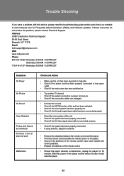
...the player for Frequently Asked Questions (FAQs) and firmware updates. If these resources do not resolve the problem, please contact Technical Support. Address COBY Electronics Technical Support 56-65 Rust Street Maspeth, NY 11378 Email [email protected] Web www.cobyusa.com Phone 800-727-3592: Weekdays 8:...has been properly connected to the power outlet. •• Check if the main power has been switched on. •• Try another TV channel •• Check if the system connection is proper and secure. •• Check if the connection cables are damaged. •...
...the player for Frequently Asked Questions (FAQs) and firmware updates. If these resources do not resolve the problem, please contact Technical Support. Address COBY Electronics Technical Support 56-65 Rust Street Maspeth, NY 11378 Email [email protected] Web www.cobyusa.com Phone 800-727-3592: Weekdays 8:...has been properly connected to the power outlet. •• Check if the main power has been switched on. •• Try another TV channel •• Check if the system connection is proper and secure. •• Check if the connection cables are damaged. •...
Instruction Manual
Page 29
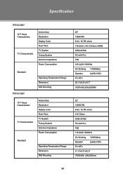
... Tuning System Antenna Impedance Power Consumption Standard TFDVD 3297 Operating Temperature Range Dimension Wall Mounting TFT Panel Characteristic TV Characteristic Active Area Resolution Display Color Pixel Pitch TV System Tuning System Antenna Impedance Power Consumption Standard Operating Temperature Range Dimension Wall Mounting 26" 1366x768 8-bit...100-240V 50/60Hz On Working 110W(Max) Speaker 2x(8Ω,10W) 0ºc-40ºc 26.1"x9.2"x19.7" VESA M5,200x200MM 32" 1366X768 8-bit, 16.7M colors 510.75mm ATSC/NTSC FS with PLL 75Ω 110-240V 50/60Hz On Working 130W(...
... Tuning System Antenna Impedance Power Consumption Standard TFDVD 3297 Operating Temperature Range Dimension Wall Mounting TFT Panel Characteristic TV Characteristic Active Area Resolution Display Color Pixel Pitch TV System Tuning System Antenna Impedance Power Consumption Standard Operating Temperature Range Dimension Wall Mounting 26" 1366x768 8-bit...100-240V 50/60Hz On Working 110W(Max) Speaker 2x(8Ω,10W) 0ºc-40ºc 26.1"x9.2"x19.7" VESA M5,200x200MM 32" 1366X768 8-bit, 16.7M colors 510.75mm ATSC/NTSC FS with PLL 75Ω 110-240V 50/60Hz On Working 130W(...


