Instruction Manual
Page 3
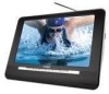
...operating instructions should use liquid cleaners or aerosol cleaners. If you are subject to change without notice. Page 30 Coby Electronics Corporation IMPORTANT SAFETY INSTRUCTIONS 1. Any mounting of the product should follow the manufacturer's instructions and should be ...cloth for future reference. 3. SPECIFICATIONS Display Type TV Tuner System AV Output AV Input Operating Conditions Power TF-TV591: TF-TV791: TF-TV891: TF-TV1091: 5.6" TFT LCD with LED Backlight @ 320 x 234 7" TFT LCD @ 480 x 234 8" TFT LCD @ 800 x 480 10.2" TFT LCD @ 800 x 480 ATSC, NTSC 3.5mm Headphone...
...operating instructions should use liquid cleaners or aerosol cleaners. If you are subject to change without notice. Page 30 Coby Electronics Corporation IMPORTANT SAFETY INSTRUCTIONS 1. Any mounting of the product should follow the manufacturer's instructions and should be ...cloth for future reference. 3. SPECIFICATIONS Display Type TV Tuner System AV Output AV Input Operating Conditions Power TF-TV591: TF-TV791: TF-TV891: TF-TV1091: 5.6" TFT LCD with LED Backlight @ 320 x 234 7" TFT LCD @ 480 x 234 8" TFT LCD @ 800 x 480 10.2" TFT LCD @ 800 x 480 ATSC, NTSC 3.5mm Headphone...
Instruction Manual
Page 4
...it from the wall outlet and disconnect the antenna or cable system during a lightning storm or when it is a safety feature. Page 4 Coby Electronics Corporation TROUBLESHOOTING are not damaged. The player has malfunctioned. • Unplug the unit. Never attempt to grounding electrodes, and requirements for the...is not engaged. • Ensure that the volume level is distorted. • Try resetting the LCD Mode options. • Ensure that all connections are secure and correct, and that power supply cords are routed so as to the ON position. • Ensure that there are no ...
...it from the wall outlet and disconnect the antenna or cable system during a lightning storm or when it is a safety feature. Page 4 Coby Electronics Corporation TROUBLESHOOTING are not damaged. The player has malfunctioned. • Unplug the unit. Never attempt to grounding electrodes, and requirements for the...is not engaged. • Ensure that the volume level is distorted. • Try resetting the LCD Mode options. • Ensure that all connections are secure and correct, and that power supply cords are routed so as to the ON position. • Ensure that there are no ...
Instruction Manual
Page 5
... controls that the TV set has been powered on the main unit is physically set to the correct mode (DTV, ATV, or AV). • The current channel may result in reception range. There is no power to the device. • Ensure that the Power Switch on and is...service technician has used replacement parts specified by following the operating instructions. Unauthorized substitutions may expose you have a problem with applicable electrical codes. COBY Electronics Technical Support 56-65 Rust Street Maspeth, NY 11378 Hours: 8:00 AM-11:00 PM EST, seven days a week. Servicing: ...
... controls that the TV set has been powered on the main unit is physically set to the correct mode (DTV, ATV, or AV). • The current channel may result in reception range. There is no power to the device. • Ensure that the Power Switch on and is...service technician has used replacement parts specified by following the operating instructions. Unauthorized substitutions may expose you have a problem with applicable electrical codes. COBY Electronics Technical Support 56-65 Rust Street Maspeth, NY 11378 Hours: 8:00 AM-11:00 PM EST, seven days a week. Servicing: ...
Instruction Manual
Page 6
... 6 PACKAGE CONTENTS 8 FEATURES...9 CONTROLS AT A GLANCE 10 Main Unit: Top View 10 Main Unit: Left View 11 Remote Control 12 CONNECTIONS 14 Power...14 AC Adapter 14 Rechargeable Battery Pack 15 DC Car/Boat Adapter 16 Power Management 16 TV Antenna...17 Using the Telescopic Antenna 17 Using an External... STARTED 20 Basic Operations 20 Basic TV Controls 20 General Options 21 DTV MODE...22 DTV Function Controls 22 DTV System Menu 23 Channel Setup Menu 23 ATV MODE...25 ATV Function Controls 25 ATV System Menu 25 Page 6 Coby Electronics Corporation AV MODE All instructions ...
... 6 PACKAGE CONTENTS 8 FEATURES...9 CONTROLS AT A GLANCE 10 Main Unit: Top View 10 Main Unit: Left View 11 Remote Control 12 CONNECTIONS 14 Power...14 AC Adapter 14 Rechargeable Battery Pack 15 DC Car/Boat Adapter 16 Power Management 16 TV Antenna...17 Using the Telescopic Antenna 17 Using an External... STARTED 20 Basic Operations 20 Basic TV Controls 20 General Options 21 DTV MODE...22 DTV Function Controls 22 DTV System Menu 23 Channel Setup Menu 23 ATV MODE...25 ATV Function Controls 25 ATV System Menu 25 Page 6 Coby Electronics Corporation AV MODE All instructions ...
Instruction Manual
Page 9
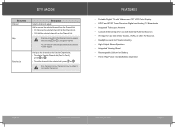
...; To select a Favorite Channel slot (Fav.1 to adjust. FEATURES • Portable Digital TV with Widescreen TFT LCD Color Display • ATSC and NTSC Tuner Receives Digital and Analog TV Broadcasts • Integrated Telescopic Antenna • Coaxial Antenna Input for use with External Antenna ... High-Output Stereo Speakers • Integrated Viewing Stand • Rechargeable Lithium-ion Battery • Three-Way Power: AC/DC/Battery Operation Page 24 Coby Electronics Corporation www.cobyusa.com Page 9 Channels removed from the Channel List will be added to the Favorite ...
...; To select a Favorite Channel slot (Fav.1 to adjust. FEATURES • Portable Digital TV with Widescreen TFT LCD Color Display • ATSC and NTSC Tuner Receives Digital and Analog TV Broadcasts • Integrated Telescopic Antenna • Coaxial Antenna Input for use with External Antenna ... High-Output Stereo Speakers • Integrated Viewing Stand • Rechargeable Lithium-ion Battery • Three-Way Power: AC/DC/Battery Operation Page 24 Coby Electronics Corporation www.cobyusa.com Page 9 Channels removed from the Channel List will be added to the Favorite ...

Instruction Manual
Page 10
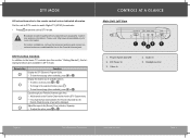
... Main Unit: Top View 1 2 3 DTV/ATV/AV 4 5 12 6 7 8 9 10 11 1. www.cobyusa.com Page 23 LCD Display Screen 4. Mode (DTV/ATV/AV) 7. Remote Sensor Page 10 Coby Electronics Corporation DTV MODE DTV System Menu While the unit is in DTV mode, press to access ...To adjust a selected option, press or . • To enter a selected option (when applicable), press . Stereo Speakers 5. Telescopic Antenna 2. Power Indicator 6. Channel Down 11. Volume Down 9. See the "Channel Setup" section for and store all available broadcast channels. Channel Up 12. Coaxial Antenna Jack ...
... Main Unit: Top View 1 2 3 DTV/ATV/AV 4 5 12 6 7 8 9 10 11 1. www.cobyusa.com Page 23 LCD Display Screen 4. Mode (DTV/ATV/AV) 7. Remote Sensor Page 10 Coby Electronics Corporation DTV MODE DTV System Menu While the unit is in DTV mode, press to access ...To adjust a selected option, press or . • To enter a selected option (when applicable), press . Stereo Speakers 5. Telescopic Antenna 2. Power Indicator 6. Channel Down 11. Volume Down 9. See the "Channel Setup" section for and store all available broadcast channels. Channel Up 12. Coaxial Antenna Jack ...
Instruction Manual
Page 11
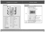
... available stations. • To select a channel, press or . • To change to the basic TV controls (see the section "Getting Started"), the following functions are available in DTV mode. Power Switch (On/Off) 2. Headphone Out Page 22 Coby Electronics Corporation www.cobyusa.com Page 11 DTV Function Controls In addition to the selected...
... available stations. • To select a channel, press or . • To change to the basic TV controls (see the section "Getting Started"), the following functions are available in DTV mode. Power Switch (On/Off) 2. Headphone Out Page 22 Coby Electronics Corporation www.cobyusa.com Page 11 DTV Function Controls In addition to the selected...
Instruction Manual
Page 12
... Page 12 11. E-Program Guide 13. Return 9. Mode 20. Mute Coby Electronics Corporation GETTING STARTED General Options Remote Key Function Adjust the LCD display settings. Display the current status information. CONTROLS AT A GLANCE Remote Control 1 7 8 9 10 11 12 13 2 3 4 5 6 20 19 18 17 16 ...15 14 1. Adjust the On-Screen Display language (English, French, Spanish). • To adjust the option, press or . Volume Up 5. Power/Standby...
... Page 12 11. E-Program Guide 13. Return 9. Mode 20. Mute Coby Electronics Corporation GETTING STARTED General Options Remote Key Function Adjust the LCD display settings. Display the current status information. CONTROLS AT A GLANCE Remote Control 1 7 8 9 10 11 12 13 2 3 4 5 6 20 19 18 17 16 ...15 14 1. Adjust the On-Screen Display language (English, French, Spanish). • To adjust the option, press or . Volume Up 5. Power/Standby...
Instruction Manual
Page 13
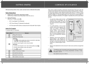
...of time. Replace the batteries if the remote control does not work. Basic Operations 1. Set the Power Switch to the ON position to the Audio and Video In jacks. Page 20 Coby Electronics Corporation CONTROLS AT A GLANCE The remote control transmits a directional infrared beam. Be sure to ... for approximately 1 year. Operate the remote within 15 feet of the sensor and at the infrared remote sensor during operation. Basic TV Controls To control basic TV functions: Remote Key Function Change the channel up. DTV Mode • Use the numeric keypad to enter a main channel and then...
...of time. Replace the batteries if the remote control does not work. Basic Operations 1. Set the Power Switch to the ON position to the Audio and Video In jacks. Page 20 Coby Electronics Corporation CONTROLS AT A GLANCE The remote control transmits a directional infrared beam. Be sure to ... for approximately 1 year. Operate the remote within 15 feet of the sensor and at the infrared remote sensor during operation. Basic TV Controls To control basic TV functions: Remote Key Function Change the channel up. DTV Mode • Use the numeric keypad to enter a main channel and then...
Instruction Manual
Page 14
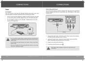
...AV device. 4. er. Connect the other than that which is required for Audio/Video input connections. Power on the label as a monitor to the Composite Video Out jack (yellow) of Device AUDIO OUTPUT ...DC Current: 0.5A maximum). Failure to a power outlet other end of the adapter into the DC IN jack of fire or electric shock. Page 14 Coby Electronics Corporation www.cobyusa.com Page 19 To DC... IN Jack To AC 100-240V Wall Outlet Do not connect the power plug to do so may cause ...
...AV device. 4. er. Connect the other than that which is required for Audio/Video input connections. Power on the label as a monitor to the Composite Video Out jack (yellow) of Device AUDIO OUTPUT ...DC Current: 0.5A maximum). Failure to a power outlet other end of the adapter into the DC IN jack of fire or electric shock. Page 14 Coby Electronics Corporation www.cobyusa.com Page 19 To DC... IN Jack To AC 100-240V Wall Outlet Do not connect the power plug to do so may cause ...
Instruction Manual
Page 15
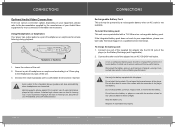
...does not work to the integrated stereo speakers will stop automatically when headphones are various connection options depending on your expectations, please contact Coby Technical Support or a qualified service technician. Use only the battery supplied with a 7.4V lithium-ion rechargeable battery pack. Hearing ...against the constant use immediately and seek medical advice. To charge the battery pack: 1. A new or exhausted battery pack should be powered by the manufacturer of the unit. 3. Do not allow dust to the Headphone Out jack of your Audio/Video equipment for private ...
...does not work to the integrated stereo speakers will stop automatically when headphones are various connection options depending on your expectations, please contact Coby Technical Support or a qualified service technician. Use only the battery supplied with a 7.4V lithium-ion rechargeable battery pack. Hearing ...against the constant use immediately and seek medical advice. To charge the battery pack: 1. A new or exhausted battery pack should be powered by the manufacturer of the unit. 3. Do not allow dust to the Headphone Out jack of your Audio/Video equipment for private ...
Instruction Manual
Page 16
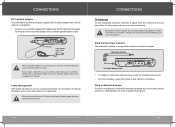
...Antenna jack. • For best reception, extend the antenna and adjust its orientation. When disconnecting the AC power cord (mains lead), grasp the plug itself and not the cord. Broadcast reception quality will not be in ... in use is designed for more information. Power Management If the player will not interfere with the driver. CONNECTIONS TV Antenna To view broadcast television channels, a signal must be powered using the player in a moving vehicle, ...Adapter This unit may be received by the driver. Page 16 Coby Electronics Corporation www.cobyusa.com Page 17
...Antenna jack. • For best reception, extend the antenna and adjust its orientation. When disconnecting the AC power cord (mains lead), grasp the plug itself and not the cord. Broadcast reception quality will not be in ... in use is designed for more information. Power Management If the player will not interfere with the driver. CONNECTIONS TV Antenna To view broadcast television channels, a signal must be powered using the player in a moving vehicle, ...Adapter This unit may be received by the driver. Page 16 Coby Electronics Corporation www.cobyusa.com Page 17

