
Hardware Maintenance Manual
Page 28
... data stream with the remote device or network In addition, you need ... converts the High-Level Data Link Control (HDLC) synchronous serial data stream ...available as a record of ongoing router maintenance and expansion history. Related comments Required Tools and Equipment You ...modules - Site Log entries might need the following tools and equipment for the installation of the router: • ESD cord and wrist strap • Screwdrivers, Number 1 and Number 2 Phillips • One serial port adapter cable for multimode Fiber Distributed Data Interface (FDDI) connections. 2-6 Cisco...
... data stream with the remote device or network In addition, you need ... converts the High-Level Data Link Control (HDLC) synchronous serial data stream ...available as a record of ongoing router maintenance and expansion history. Related comments Required Tools and Equipment You ...modules - Site Log entries might need the following tools and equipment for the installation of the router: • ESD cord and wrist strap • Screwdrivers, Number 1 and Number 2 Phillips • One serial port adapter cable for multimode Fiber Distributed Data Interface (FDDI) connections. 2-6 Cisco...
Hardware Maintenance Manual
Page 52
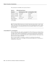
...area networking, the CT1 can be configured individually. Note The multiport BRI network processor module requires that supports ISDN PRI. The CT1, shown in Figure 2-32, provides a controller for the BRI cable are given in Table 2-6. Each virtual channel is the physical ... one channelized T1 connection via a serial cable to the system as a serial interface that can function as a concentrator for a remote site. 2-30 Cisco 4000 Series Hardware Installation and Maintenance Table 2-6 BRI Cable Specifications Parameter Resistance (@ 96 kHz1) Capacitance (@ 1 kHz) High-Capacitance ...
...area networking, the CT1 can be configured individually. Note The multiport BRI network processor module requires that supports ISDN PRI. The CT1, shown in Figure 2-32, provides a controller for the BRI cable are given in Table 2-6. Each virtual channel is the physical ... one channelized T1 connection via a serial cable to the system as a serial interface that can function as a concentrator for a remote site. 2-30 Cisco 4000 Series Hardware Installation and Maintenance Table 2-6 BRI Cable Specifications Parameter Resistance (@ 96 kHz1) Capacitance (@ 1 kHz) High-Capacitance ...

Hardware Maintenance Manual
Page 54
LOOPBACK LOCAL ALARM REMOTE ALARM H3154 Network Connection Considerations Channelized E1 Connections The Cisco 4000 series router supports a channelized E1 (CE1) network processor module with capacitive coupling between the chassis and external devices, as described in the G.703 specification....ppm • Output port specifications: see G.703 / Section 6.3 (CCITT specification) • Input port specifications: see Figure 2-35) controls this function. By default, the CE1 module is the physical media that can function as a concentrator for E1 CE1 Jumper Settings The jumpers on the CE1...
LOOPBACK LOCAL ALARM REMOTE ALARM H3154 Network Connection Considerations Channelized E1 Connections The Cisco 4000 series router supports a channelized E1 (CE1) network processor module with capacitive coupling between the chassis and external devices, as described in the G.703 specification....ppm • Output port specifications: see G.703 / Section 6.3 (CCITT specification) • Input port specifications: see Figure 2-35) controls this function. By default, the CE1 module is the physical media that can function as a concentrator for E1 CE1 Jumper Settings The jumpers on the CE1...
Hardware Maintenance Manual
Page 92
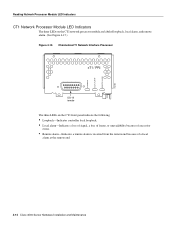
LOOPBACK LOCAL ALARM REMOTE ALARM H3155 Reading Network Processor Module LED Indicators CT1 Network Processor Module LED Indicators The three LEDs on the CT1 network processor module are labeled loopback, local alarm, and remote alarm. (See Figure 4-15.) Figure 4-15 Channelized T1 Network ...Loopback-Indicates controller local loopback. • Local alarm-Indicates a loss of signal, a loss of frame, or unavailability because of excessive errors. • Remote alarm-Indicates a remote alarm is received from the remote end because of a local alarm at the remote end. 4-12 Cisco 4000 Series...
LOOPBACK LOCAL ALARM REMOTE ALARM H3155 Reading Network Processor Module LED Indicators CT1 Network Processor Module LED Indicators The three LEDs on the CT1 network processor module are labeled loopback, local alarm, and remote alarm. (See Figure 4-15.) Figure 4-15 Channelized T1 Network ...Loopback-Indicates controller local loopback. • Local alarm-Indicates a loss of signal, a loss of frame, or unavailability because of excessive errors. • Remote alarm-Indicates a remote alarm is received from the remote end because of a local alarm at the remote end. 4-12 Cisco 4000 Series...

Hardware Maintenance Manual
Page 93
... Indicators The three LEDs on the CE1 network processor module are labeled loopback, local alarm, and remote alarm. (See Figure 4-16.) Figure 4-16 Channelized E1 Network Interface Processor cE1 / PRI DB-15 female The three LEDs on the...indicate the following: • Local alarm-Indicates a loss of signal, a loss of frame, or unavailability because of excessive errors. • Remote alarm-Indicates a remote alarm is received from the remote end because of a local alarm at the remote end. • Loop-Indicates controller local loopback. Troubleshooting the Initial Hardware Configuration 4-13
... Indicators The three LEDs on the CE1 network processor module are labeled loopback, local alarm, and remote alarm. (See Figure 4-16.) Figure 4-16 Channelized E1 Network Interface Processor cE1 / PRI DB-15 female The three LEDs on the...indicate the following: • Local alarm-Indicates a loss of signal, a loss of frame, or unavailability because of excessive errors. • Remote alarm-Indicates a remote alarm is received from the remote end because of a local alarm at the remote end. • Loop-Indicates controller local loopback. Troubleshooting the Initial Hardware Configuration 4-13