
Hardware Maintenance Manual
Page 16
... replacing single in-line memory modules (SIMMs). • Appendix A, "Cabling Specifications," provides cable illustrations, cable pinouts, and signal descriptions for the console and auxiliary ports, synchronous serial cables, and Ethernet (AUI) cables. • Appendix B, "Cisco 4000 Series Virtual Configuration Register," describes the Cisco 4000-M virtual configuration register and procedures for changing the factory-default settings...
... replacing single in-line memory modules (SIMMs). • Appendix A, "Cabling Specifications," provides cable illustrations, cable pinouts, and signal descriptions for the console and auxiliary ports, synchronous serial cables, and Ethernet (AUI) cables. • Appendix B, "Cisco 4000 Series Virtual Configuration Register," describes the Cisco 4000-M virtual configuration register and procedures for changing the factory-default settings...

Hardware Maintenance Manual
Page 21
... MB 1. Table 1-2 lists the processor and memory specifications for the Cisco 4000 series routers. Table 1-2 Cisco 4000 Series Processor and Memory Specifications Description Processor Main Memory (DRAM)2 Cisco 4000-M Cisco 4500-M Cisco 4700 40-MHz Motorola 68EC030 100-MHz IDT Orion RISC1 133-MHz... series routers. Table 1-1 Cisco 4000 Series Physical Specifications Description Design Specification Dimensions (W x D x H) 17.6" x 17.7" x 3.4" (44.7 cm x 45 cm x 8.6 cm) Weight 24 lb (10.9 kg) (including the chassis and network processor modules) Power Wire Gauge for DC-Input Power ...
... MB 1. Table 1-2 lists the processor and memory specifications for the Cisco 4000 series routers. Table 1-2 Cisco 4000 Series Processor and Memory Specifications Description Processor Main Memory (DRAM)2 Cisco 4000-M Cisco 4500-M Cisco 4700 40-MHz Motorola 68EC030 100-MHz IDT Orion RISC1 133-MHz... series routers. Table 1-1 Cisco 4000 Series Physical Specifications Description Design Specification Dimensions (W x D x H) 17.6" x 17.7" x 3.4" (44.7 cm x 45 cm x 8.6 cm) Weight 24 lb (10.9 kg) (including the chassis and network processor modules) Power Wire Gauge for DC-Input Power ...
Hardware Maintenance Manual
Page 23
Slot numbering - This chapter includes the cabling requirements for inspecting the system are included in your equipment - Instructions for the installation site, descriptions of additional equipment you will need to complete the installation, and the environmental conditions the site must meet to protect you can check off after ...
Slot numbering - This chapter includes the cabling requirements for inspecting the system are included in your equipment - Instructions for the installation site, descriptions of additional equipment you will need to complete the installation, and the environmental conditions the site must meet to protect you can check off after ...

Hardware Maintenance Manual
Page 45
...: router# configure terminal interface serial 0 nrzi-encoding ^Z To disable NRZI encoding on the Four-Port Serial Module All Cisco 4000 series router serial interfaces support CRC-CCITT, a 16-bit cyclic redundancy check (CRC). For complete command descriptions and instructions, refer to decode signals, rather than determining absolute values. NRZ signals maintain constant voltage...
...: router# configure terminal interface serial 0 nrzi-encoding ^Z To disable NRZI encoding on the Four-Port Serial Module All Cisco 4000 series router serial interfaces support CRC-CCITT, a 16-bit cyclic redundancy check (CRC). For complete command descriptions and instructions, refer to decode signals, rather than determining absolute values. NRZ signals maintain constant voltage...

Hardware Maintenance Manual
Page 46
...options. (Note in the example that universal serial means the four port serial module.) The following example: buffer size 2108 Universal Serial: DTE V.24 (RS-232..., 0 drops; If a cable is attached to the appropriate software publications. 2-24 Cisco 4000 Series Hardware Installation and Maintenance For complete command descriptions and instructions, refer to the port, the cable type would be shown, as no... the clock rate. Network Connection Considerations router> show interface s 0 Serial 0 is up, line protocol is up Hardware is HD64570 Internet address is 193.195.74.236, subnet mask is 255...
...options. (Note in the example that universal serial means the four port serial module.) The following example: buffer size 2108 Universal Serial: DTE V.24 (RS-232..., 0 drops; If a cable is attached to the appropriate software publications. 2-24 Cisco 4000 Series Hardware Installation and Maintenance For complete command descriptions and instructions, refer to the port, the cable type would be shown, as no... the clock rate. Network Connection Considerations router> show interface s 0 Serial 0 is up, line protocol is up Hardware is HD64570 Internet address is 193.195.74.236, subnet mask is 255...

Hardware Maintenance Manual
Page 81
... for information on how to help identify the cause. If you cannot locate the source of the problem you received the new chassis • Brief description of your system, follow : • Problem Solving • Environmental Reporting Features • Reading Front-Panel LED Indicators • Reading Network Processor...
... for information on how to help identify the cause. If you cannot locate the source of the problem you received the new chassis • Brief description of your system, follow : • Problem Solving • Environmental Reporting Features • Reading Front-Panel LED Indicators • Reading Network Processor...

Hardware Maintenance Manual
Page 84
...network processor module are all visible through cutouts in position to the three network processor modules, if present...Module LED Indicators The network processor module LEDs are labeled as shown in Figure 4-2. (Also see Figure 2-5.) Figure 4-3 Single-Port Ethernet Network Processor Module LEDs H1126a AUI POL LNK RX TX Descriptions... of the chassis. The syntax of the media command follows: media-type aui | 10BaseT Details on the far right indicates that the system card...LEDs on the network processor module will be lit. When...
...network processor module are all visible through cutouts in position to the three network processor modules, if present...Module LED Indicators The network processor module LEDs are labeled as shown in Figure 4-2. (Also see Figure 2-5.) Figure 4-3 Single-Port Ethernet Network Processor Module LEDs H1126a AUI POL LNK RX TX Descriptions... of the chassis. The syntax of the media command follows: media-type aui | 10BaseT Details on the far right indicates that the system card...LEDs on the network processor module will be lit. When...

Hardware Maintenance Manual
Page 125
... register to read the configuration file in a file on the console terminal. Be sure to automatically reboot the router. Cisco 4000-M ROM Monitor C-3 Entering the Cisco 4000-M ROM Monitor Program • Display/Reset Virtual Configuration Register-The o command displays the virtual configuration register. By ...and cause the system software image to save the configuration in nonvolatile RAM, clear the ignore NVRAM contents bit (0x0040) with a description of 10 minutes. The time to run a diagnostic is good practice for you to ignore the configuration register information (sets the ...
... register to read the configuration file in a file on the console terminal. Be sure to automatically reboot the router. Cisco 4000-M ROM Monitor C-3 Entering the Cisco 4000-M ROM Monitor Program • Display/Reset Virtual Configuration Register-The o command displays the virtual configuration register. By ...and cause the system software image to save the configuration in nonvolatile RAM, clear the ignore NVRAM contents bit (0x0040) with a description of 10 minutes. The time to run a diagnostic is good practice for you to ignore the configuration register information (sets the ...
Hardware Maintenance Manual
Page 129
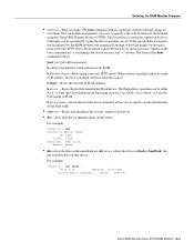
When a host is specified, either flash:, to boot the Cisco Internetwork Operating System (Cisco IOS), or bootflash:, to boot the boot image in Flash. b flash:-Boots the first file in Flash memory b device:-Boots the first file found in ... files on that source. For example: rommon 11 > dir flash: File size Checksum File name 2229799 bytes (0x220627) 0x469e C4500-k Cisco 4500-M and Cisco 4700 ROM Monitor D-3 The local device (see the description of b device following) can be booted over the network using a network TFTP server. The form of the above command, allows...
When a host is specified, either flash:, to boot the Cisco Internetwork Operating System (Cisco IOS), or bootflash:, to boot the boot image in Flash. b flash:-Boots the first file in Flash memory b device:-Boots the first file found in ... files on that source. For example: rommon 11 > dir flash: File size Checksum File name 2229799 bytes (0x220627) 0x469e C4500-k Cisco 4500-M and Cisco 4700 ROM Monitor D-3 The local device (see the description of b device following) can be booted over the network using a network TFTP server. The form of the above command, allows...
Hardware Maintenance Manual
Page 137
... (boot) C-2 Basic Rate Interface See BRI boot command D-3 boot ROMs, replacing 5-19 booting from Flash B-6 from the ROM monitor Cisco 4000-M C-2 Cisco 4500-M D-3 Cisco 4700 D-3 bootstrap clear memory contents C-2 stack trace, system software C-2 Break key (interrupt) C-1, D-1 BRI distance limitations 2-30, 3-6... Token Ring lobe 2-14 transceiver 2-11 cables safety guidelines 2-3 ungrounded 2-3 uninsulated 2-3 caution, description xvii CE1 cable A-23 network processor module 2-32 channel service unit/digital service unit See CSU/DSU chassis connecting 2-7 dimensions 1-3 opening 5-1 rear view 2-8...
... (boot) C-2 Basic Rate Interface See BRI boot command D-3 boot ROMs, replacing 5-19 booting from Flash B-6 from the ROM monitor Cisco 4000-M C-2 Cisco 4500-M D-3 Cisco 4700 D-3 bootstrap clear memory contents C-2 stack trace, system software C-2 Break key (interrupt) C-1, D-1 BRI distance limitations 2-30, 3-6... Token Ring lobe 2-14 transceiver 2-11 cables safety guidelines 2-3 ungrounded 2-3 uninsulated 2-3 caution, description xvii CE1 cable A-23 network processor module 2-32 channel service unit/digital service unit See CSU/DSU chassis connecting 2-7 dimensions 1-3 opening 5-1 rear view 2-8...
Hardware Maintenance Manual
Page 138
... command D-4 conventions serial modes 4-9 this publication xv CSU/DSU clocking on serial interface port 2-21 connection to DTE port 2-9 CT1 cables 2-31, A-22 network processor module 2-30 D danger, warnings description xvii 4 Cisco 4000 Series Hardware Installation and Maintenance
... command D-4 conventions serial modes 4-9 this publication xv CSU/DSU clocking on serial interface port 2-21 connection to DTE port 2-9 CT1 cables 2-31, A-22 network processor module 2-30 D danger, warnings description xvii 4 Cisco 4000 Series Hardware Installation and Maintenance

Hardware Maintenance Manual
Page 141
... C-2 preventing C-2 network activity indicator 4-4 connection considerations network processor module ATM 2-34 network processor modules dual serial 2-20 Ethernet 2-10 FDDI 2-27, 4-10 LED indicators 4-4 locations 5-6 removing 5-4 replacing 5-20 Token Ring 2-13 nonreturn to zero See NRZ nonreturn to zero-inverted See NRZI note, description xvi NRZ, configuring interface for NRZI, configuring interface for...
... C-2 preventing C-2 network activity indicator 4-4 connection considerations network processor module ATM 2-34 network processor modules dual serial 2-20 Ethernet 2-10 FDDI 2-27, 4-10 LED indicators 4-4 locations 5-6 removing 5-4 replacing 5-20 Token Ring 2-13 nonreturn to zero See NRZ nonreturn to zero-inverted See NRZI note, description xvi NRZ, configuring interface for NRZI, configuring interface for...
Hardware Maintenance Manual
Page 142
...2-6 registers, software configuration B-1 reinitializing hardware C-2 reload command B-2 removing network processor modules 5-4 shared-memory SIMMs 5-13 replacing Cisco 4000-M boot ROMs 5-19 component tray 5-20 network processor modules 5-20 shared-memory SIMMs 5-14 system-memory SIMMs 5-8 reset command D-3 resetting ...22 shared DRAM, size 1-3 signal descriptions Ethernet A-19-A-20 serial A-2-A-18 Token Ring A-21 signals BRI 3-8, A-22 console and auxiliary ports 3-8 SIMMs shared-memory, replacing 5-13 system-memory, replacing 5-8 single in-line memory module See SIMMs site environment 2-3 log, ...
...2-6 registers, software configuration B-1 reinitializing hardware C-2 reload command B-2 removing network processor modules 5-4 shared-memory SIMMs 5-13 replacing Cisco 4000-M boot ROMs 5-19 component tray 5-20 network processor modules 5-20 shared-memory SIMMs 5-14 system-memory SIMMs 5-8 reset command D-3 resetting ...22 shared DRAM, size 1-3 signal descriptions Ethernet A-19-A-20 serial A-2-A-18 Token Ring A-21 signals BRI 3-8, A-22 console and auxiliary ports 3-8 SIMMs shared-memory, replacing 5-13 system-memory, replacing 5-8 single in-line memory module See SIMMs site environment 2-3 log, ...
Hardware Maintenance Manual
Page 143
... (test) C-3 telephone jacks 2-3 temperature nonoperating 1-3 problem causes 4-3 problem indications 4-3 warning 4-3 terminal padding command 3-2 time saver, description xvi Token Ring connecting 3-2 connecting cable 3-2 connections 2-13 LED indications 4-5 port, location 2-7 tools required for installation 2-6 transceiver cable...11 transmit, Ethernet LED 4-5 tray, component, replacing 5-20 troubleshooting cables 4-2 initial hardware configuration 4-1 network processor modules 4-2 power and cooling systems 4-2 U unit numbering 2-7 United Kingdom operating condition warnings E-1 UniverCD xv V V.35...
... (test) C-3 telephone jacks 2-3 temperature nonoperating 1-3 problem causes 4-3 problem indications 4-3 warning 4-3 terminal padding command 3-2 time saver, description xvi Token Ring connecting 3-2 connecting cable 3-2 connections 2-13 LED indications 4-5 port, location 2-7 tools required for installation 2-6 transceiver cable...11 transmit, Ethernet LED 4-5 tray, component, replacing 5-20 troubleshooting cables 4-2 initial hardware configuration 4-1 network processor modules 4-2 power and cooling systems 4-2 U unit numbering 2-7 United Kingdom operating condition warnings E-1 UniverCD xv V V.35...