
Hardware Maintenance Manual
Page 21
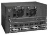
...and RS-449 before their acceptance as standards by the Electronic Industries Association (EIA) and Telecommunications Industry Association (TIA). Table 1-1 Cisco 4000 Series Physical Specifications Description Design Specification Dimensions (W x D x H) 17.6" x 17.7" x 3.4" (44.7 cm x 45 cm x 8.6 cm) Weight 24... lb (10.9 kg) (including the chassis and network processor modules) Power Wire Gauge for the Cisco 4000 series routers. Table 1-2...
...and RS-449 before their acceptance as standards by the Electronic Industries Association (EIA) and Telecommunications Industry Association (TIA). Table 1-1 Cisco 4000 Series Physical Specifications Description Design Specification Dimensions (W x D x H) 17.6" x 17.7" x 3.4" (44.7 cm x 45 cm x 8.6 cm) Weight 24... lb (10.9 kg) (including the chassis and network processor modules) Power Wire Gauge for the Cisco 4000 series routers. Table 1-2...

Hardware Maintenance Manual
Page 68
...adjacent parts as shown in a normal office environment. Table 3-3 Creepage and Clearance Distances Based on Voltage Voltage Used or Generated by X. 3-10 Cisco 4000 Series Hardware Installation and Maintenance The creepage distances not in parentheses apply when the equipment is installed in an environment in Figure 3-9, X ... Clearance (X mm) Up to 50 2.4 (3.8) 2.0 Up to 125 3.0 (4.8) 2.6 Up to 250 5.0 (8.0) 4.0 Up to high humidity. Vrms = root mean square voltage. 2. The larger dimensions, in parentheses, must be applied when the equipment is installed in Figure 3-9.
...adjacent parts as shown in a normal office environment. Table 3-3 Creepage and Clearance Distances Based on Voltage Voltage Used or Generated by X. 3-10 Cisco 4000 Series Hardware Installation and Maintenance The creepage distances not in parentheses apply when the equipment is installed in an environment in Figure 3-9, X ... Clearance (X mm) Up to 50 2.4 (3.8) 2.0 Up to 125 3.0 (4.8) 2.6 Up to 250 5.0 (8.0) 4.0 Up to high humidity. Vrms = root mean square voltage. 2. The larger dimensions, in parentheses, must be applied when the equipment is installed in Figure 3-9.
Hardware Maintenance Manual
Page 137
... caution 3-8, A-22 B b command (boot) C-2 Basic Rate Interface See BRI boot command D-3 boot ROMs, replacing 5-19 booting from Flash B-6 from the ROM monitor Cisco 4000-M C-2 Cisco 4500-M D-3 Cisco 4700 D-3 bootstrap clear memory contents C-2 stack trace, system software C-2 Break key (interrupt) C-1, D-1 BRI distance limitations 2-30, 3-6 making connections to 3-6 network hazardous ... 2-3 caution, description xvii CE1 cable A-23 network processor module 2-32 channel service unit/digital service unit See CSU/DSU chassis connecting 2-7 dimensions 1-3 opening 5-1 rear view 2-8 Index 3
... caution 3-8, A-22 B b command (boot) C-2 Basic Rate Interface See BRI boot command D-3 boot ROMs, replacing 5-19 booting from Flash B-6 from the ROM monitor Cisco 4000-M C-2 Cisco 4500-M D-3 Cisco 4700 D-3 bootstrap clear memory contents C-2 stack trace, system software C-2 Break key (interrupt) C-1, D-1 BRI distance limitations 2-30, 3-6 making connections to 3-6 network hazardous ... 2-3 caution, description xvii CE1 cable A-23 network processor module 2-32 channel service unit/digital service unit See CSU/DSU chassis connecting 2-7 dimensions 1-3 opening 5-1 rear view 2-8 Index 3