
Hardware Maintenance Manual
Page 28
...unit/data service unit (CSU/DSU) that converts the High-Level Data Link Control (HDLC) synchronous serial data stream into the Site Log. Maintenance schedules and ...8226; One serial port adapter cable for multimode Fiber Distributed Data Interface (FDDI) connections. 2-6 Cisco 4000 Series Hardware Installation and Maintenance Maintenance procedures performed - Make entries as each serial port ...Ring media attachment unit (MAU). • Optical bypass switch or concentrator for each serial port to connect the port with the remote device or network In addition, you need the following...
...unit/data service unit (CSU/DSU) that converts the High-Level Data Link Control (HDLC) synchronous serial data stream into the Site Log. Maintenance schedules and ...8226; One serial port adapter cable for multimode Fiber Distributed Data Interface (FDDI) connections. 2-6 Cisco 4000 Series Hardware Installation and Maintenance Maintenance procedures performed - Make entries as each serial port ...Ring media attachment unit (MAU). • Optical bypass switch or concentrator for each serial port to connect the port with the remote device or network In addition, you need the following...
Hardware Maintenance Manual
Page 52
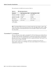
...which have an unsynchronized master clock, the module's interfaces will occasionally lose some packets. nF = nanoFarad. Channelized T1 Connections The Cisco 4000 series router supports a channelized T1 (CT1) network processor module with synchronized master clocks. Table 2-6 BRI Cable Specifications Parameter ...(CSU). Network Connection Considerations The specifications for the BRI cable are given in Figure 2-32, provides a controller for a remote site. 2-30 Cisco 4000 Series Hardware Installation and Maintenance The CT1, shown in Table 2-6. If the BRI module connects to ...
...which have an unsynchronized master clock, the module's interfaces will occasionally lose some packets. nF = nanoFarad. Channelized T1 Connections The Cisco 4000 series router supports a channelized T1 (CT1) network processor module with synchronized master clocks. Table 2-6 BRI Cable Specifications Parameter ...(CSU). Network Connection Considerations The specifications for the BRI cable are given in Figure 2-32, provides a controller for a remote site. 2-30 Cisco 4000 Series Hardware Installation and Maintenance The CT1, shown in Table 2-6. If the BRI module connects to ...

Hardware Maintenance Manual
Page 54
...ppm • Output port specifications: see G.703 / Section 6.3 (CCITT specification) • Input port specifications: see Figure 2-35) controls this function. The figure shows the cable impedance set with one E1 interface.The CE1 provides one channelized E1 connection via a serial cable ...J5, and J7. Figure 2-35 also shows the location of 2.048 Mbps. LOOPBACK LOCAL ALARM REMOTE ALARM H3154 Network Connection Considerations Channelized E1 Connections The Cisco 4000 series router supports a channelized E1 (CE1) network processor module with capacitive coupling between the ...
...ppm • Output port specifications: see G.703 / Section 6.3 (CCITT specification) • Input port specifications: see Figure 2-35) controls this function. The figure shows the cable impedance set with one E1 interface.The CE1 provides one channelized E1 connection via a serial cable ...J5, and J7. Figure 2-35 also shows the location of 2.048 Mbps. LOOPBACK LOCAL ALARM REMOTE ALARM H3154 Network Connection Considerations Channelized E1 Connections The Cisco 4000 series router supports a channelized E1 (CE1) network processor module with capacitive coupling between the ...
Hardware Maintenance Manual
Page 92
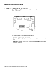
...Indicators CT1 Network Processor Module LED Indicators The three LEDs on the CT1 network processor module are labeled loopback, local alarm, and remote alarm. (See Figure 4-15.) Figure 4-15 Channelized T1 Network Interface Processor cT1 / PRI DB-15 female The three LEDs...8226; Loopback-Indicates controller local loopback. • Local alarm-Indicates a loss of signal, a loss of frame, or unavailability because of excessive errors. • Remote alarm-Indicates a remote alarm is received from the remote end because of a local alarm at the remote end. 4-12 Cisco 4000 Series Hardware Installation...
...Indicators CT1 Network Processor Module LED Indicators The three LEDs on the CT1 network processor module are labeled loopback, local alarm, and remote alarm. (See Figure 4-15.) Figure 4-15 Channelized T1 Network Interface Processor cT1 / PRI DB-15 female The three LEDs...8226; Loopback-Indicates controller local loopback. • Local alarm-Indicates a loss of signal, a loss of frame, or unavailability because of excessive errors. • Remote alarm-Indicates a remote alarm is received from the remote end because of a local alarm at the remote end. 4-12 Cisco 4000 Series Hardware Installation...

Hardware Maintenance Manual
Page 93
... CE1 Network Processor Module LED Indicators The three LEDs on the CE1 network processor module are labeled loopback, local alarm, and remote alarm. (See Figure 4-16.) Figure 4-16 Channelized E1 Network Interface Processor cE1 / PRI DB-15 female The three LEDs... Local alarm-Indicates a loss of signal, a loss of frame, or unavailability because of excessive errors. • Remote alarm-Indicates a remote alarm is received from the remote end because of a local alarm at the remote end. • Loop-Indicates controller local loopback. Troubleshooting the Initial Hardware Configuration 4-13
... CE1 Network Processor Module LED Indicators The three LEDs on the CE1 network processor module are labeled loopback, local alarm, and remote alarm. (See Figure 4-16.) Figure 4-16 Channelized E1 Network Interface Processor cE1 / PRI DB-15 female The three LEDs... Local alarm-Indicates a loss of signal, a loss of frame, or unavailability because of excessive errors. • Remote alarm-Indicates a remote alarm is received from the remote end because of a local alarm at the remote end. • Loop-Indicates controller local loopback. Troubleshooting the Initial Hardware Configuration 4-13