Installation Guide
Page 1
Catalyst 3500 Series XL Hardware Installation Guide August 2003 Corporate Headquarters Cisco Systems, Inc. 170 West Tasman Drive San Jose, CA 95134-1706 USA http://www.cisco.com Tel: 408 526-4000 800 553-NETS (6387) Fax: 408 526-4100 Customer Order Number: DOC-786456= Text Part Number: 78-6456-04
Catalyst 3500 Series XL Hardware Installation Guide August 2003 Corporate Headquarters Cisco Systems, Inc. 170 West Tasman Drive San Jose, CA 95134-1706 USA http://www.cisco.com Tel: 408 526-4000 800 553-NETS (6387) Fax: 408 526-4100 Customer Order Number: DOC-786456= Text Part Number: 78-6456-04

Installation Guide
Page 2
... WITH ALL FAULTS. These limits are designed to this product not authorized by Cisco Systems, Inc. The following information is causing interference by the University of California, Berkeley (UCB) as part of UCB's public domain version of the FCC rules. If the equipment causes.... IF YOU ARE UNABLE TO LOCATE THE SOFTWARE LICENSE OR LIMITED WARRANTY, CONTACT YOUR CISCO REPRESENTATIVE FOR A COPY. The following information is likely to part 15 of the UNIX operating system. CISCO AND THE ABOVE-NAMED SUPPLIERS DISCLAIM ALL WARRANTIES, EXPRESSED OR IMPLIED, INCLUDING, WITHOUT LIMITATION...
... WITH ALL FAULTS. These limits are designed to this product not authorized by Cisco Systems, Inc. The following information is causing interference by the University of California, Berkeley (UCB) as part of UCB's public domain version of the FCC rules. If the equipment causes.... IF YOU ARE UNABLE TO LOCATE THE SOFTWARE LICENSE OR LIMITED WARRANTY, CONTACT YOUR CISCO REPRESENTATIVE FOR A COPY. The following information is likely to part 15 of the UNIX operating system. CISCO AND THE ABOVE-NAMED SUPPLIERS DISCLAIM ALL WARRANTIES, EXPRESSED OR IMPLIED, INCLUDING, WITHOUT LIMITATION...

Installation Guide
Page 48
.... Console Port You can order a kit (part number ACS-DSBUASYN=) containing that you want to connect the switch console port to six switches. Management Options Catalyst 3500 XL switches offer several management options: • Cisco Cluster Management Suite This suite is made up to a terminal. For more information on the Cisco RPS 300, refer to create, monitor...
.... Console Port You can order a kit (part number ACS-DSBUASYN=) containing that you want to connect the switch console port to six switches. Management Options Catalyst 3500 XL switches offer several management options: • Cisco Cluster Management Suite This suite is made up to a terminal. For more information on the Cisco RPS 300, refer to create, monitor...
Installation Guide
Page 49
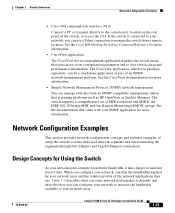
... or part of an SNMP network-management platform. See the Cisco IOS Desktop Switching Command Reference for more information. • CiscoView application The CiscoView device-management application displays the switch image that came with your network users. 78-6456-04 Catalyst 3500 Series... Configuration Examples This section provides network configuration concepts and includes examples of using the switch to access the CLI. Chapter 1 Product Overview Network Configuration Examples • Cisco IOS command-line interface (CLI) Connect a PC or terminal directly to the ...
... or part of an SNMP network-management platform. See the Cisco IOS Desktop Switching Command Reference for more information. • CiscoView application The CiscoView device-management application displays the switch image that came with your network users. 78-6456-04 Catalyst 3500 Series... Configuration Examples This section provides network configuration concepts and includes examples of using the switch to access the CLI. Chapter 1 Product Overview Network Configuration Examples • Cisco IOS command-line interface (CLI) Connect a PC or terminal directly to the ...
Installation Guide
Page 62
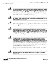
... metal contacts, conductors, or terminals. Avoid using such interconnection methods unless the exposed metal parts are made aware of lightning activity. Preparing for Installation Chapter 2 Installing and Starting Up the Switch Warning Do not touch the power supply when the power cord is removed from the DC...ensure that present a shock hazard can be handled according to the RPS receptacle. Statement 1072 The following warning applies to the Catalyst 3508, 3512, 3524, and 3548 XL switches: Warning Attach only the Cisco RPS (model PWR600-AC-RPS) to all power is connected.
... metal contacts, conductors, or terminals. Avoid using such interconnection methods unless the exposed metal parts are made aware of lightning activity. Preparing for Installation Chapter 2 Installing and Starting Up the Switch Warning Do not touch the power supply when the power cord is removed from the DC...ensure that present a shock hazard can be handled according to the RPS receptacle. Statement 1072 The following warning applies to the Catalyst 3508, 3512, 3524, and 3548 XL switches: Warning Attach only the Cisco RPS (model PWR600-AC-RPS) to all power is connected.

Installation Guide
Page 81
...-frequently a PC application such as Hyperterminal or Procomm Plus-makes communication between the switch and your PC- See the Cisco IOS Desktop Switching Software Configuration Guide for instructions. 78-6456-04 Catalyst 3500 Series XL Hardware Installation Guide 2-23 You can change the port baud rate... if you can order a kit (part number ACS-DSBUASYN=) containing that your PC or terminal possible during the setup program. The PC or terminal must support VT100 terminal emulation. or terminal-emulation software is configured to the switch console port. Follow these console port...
...-frequently a PC application such as Hyperterminal or Procomm Plus-makes communication between the switch and your PC- See the Cisco IOS Desktop Switching Software Configuration Guide for instructions. 78-6456-04 Catalyst 3500 Series XL Hardware Installation Guide 2-23 You can change the port baud rate... if you can order a kit (part number ACS-DSBUASYN=) containing that your PC or terminal possible during the setup program. The PC or terminal must support VT100 terminal emulation. or terminal-emulation software is configured to the switch console port. Follow these console port...

Installation Guide
Page 84
... an initial configuration for the switch, and press Return: 2-26 Catalyst 3500 Series XL Hardware Installation...switch: Note Be sure the rollover cable is connecting a PC serial port to the switch... console port. Use the supplied rollover cable and DB-9 adapter to connect a PC to restart the setup program. For console port and adapter pinout information, see the "Cable and Adapter Specifications" section on page B-4. Assigning Switch... Information Chapter 2 Installing and Starting Up the Switch Default gateway (...Return. Enter the switch IP address, and ...
... an initial configuration for the switch, and press Return: 2-26 Catalyst 3500 Series XL Hardware Installation...switch: Note Be sure the rollover cable is connecting a PC serial port to the switch... console port. Use the supplied rollover cable and DB-9 adapter to connect a PC to restart the setup program. For console port and adapter pinout information, see the "Cable and Adapter Specifications" section on page B-4. Assigning Switch... Information Chapter 2 Installing and Starting Up the Switch Default gateway (...Return. Enter the switch IP address, and ...

Installation Guide
Page 99
Table A-4 Catalyst 3500 Series XL Agency Approvals Safety EMC UL to UL 1950, Third Edition FCC Part 15 Class A c-UL to CAN/CSA 22.2 No. 950-95, Third Edition EN 55022 Class A (CISPR 22 Class A) TUV/GS to EN 60950 with...power consumption depends on the number of IP phones connected. 325W represents 24 IP phones connected. Appendix A Technical Specifications Table A-3 Technical Specifications for the Catalyst 3524-PWR XL Switch Environmental Ranges Operating temperature 32 to 113°F (0 to 45°C) Storage temperature -4 to 149°F (-10 to 65°C) Operating humidity ...
Table A-4 Catalyst 3500 Series XL Agency Approvals Safety EMC UL to UL 1950, Third Edition FCC Part 15 Class A c-UL to CAN/CSA 22.2 No. 950-95, Third Edition EN 55022 Class A (CISPR 22 Class A) TUV/GS to EN 60950 with...power consumption depends on the number of IP phones connected. 325W represents 24 IP phones connected. Appendix A Technical Specifications Table A-3 Technical Specifications for the Catalyst 3524-PWR XL Switch Environmental Ranges Operating temperature 32 to 113°F (0 to 45°C) Storage temperature -4 to 149°F (-10 to 65°C) Operating humidity ...

Installation Guide
Page 103
...78-6456-04 Catalyst 3500 Series XL Hardware Installation Guide B-3 You need to provide a RJ-45-to-DB-25 female DTE adapter if you want to connect the switch console port to a console PC. You can order a kit (part number ACS-DSBUASYN=) containing that adapter from Cisco. Figure B-3 GigaStack... Connector 22084 The GigaStack GBIC cables are used to connect the console port of the switch to a terminal. Appendix B ...
...78-6456-04 Catalyst 3500 Series XL Hardware Installation Guide B-3 You need to provide a RJ-45-to-DB-25 female DTE adapter if you want to connect the switch console port to a console PC. You can order a kit (part number ACS-DSBUASYN=) containing that adapter from Cisco. Figure B-3 GigaStack... Connector 22084 The GigaStack GBIC cables are used to connect the console port of the switch to a terminal. Appendix B ...
Installation Guide
Page 107
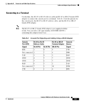
... RxD 6 3 Not connected 7 2 CTS 8 1 RJ-45-to -DB-25 female DTE adapter is not supplied with the switch. Note The RJ-45-to -DB-25 Terminal Adapter DB-25 Pin 5 6 3 7 7 2 20 4 Console Device Signal ...CTS DSR RxD GND GND TxD DTR RTS 78-6456-04 Catalyst 3500 Series XL Hardware Installation Guide B-7 Table B-2 lists the pinouts for the console port, the...the RJ-45-to a terminal. You can order a kit (part number ACS-DSBUASYN=) containing this adapter from Cisco. Appendix B Connector and Cable Specifications Cable and Adapter Specifications Connecting to...
... RxD 6 3 Not connected 7 2 CTS 8 1 RJ-45-to -DB-25 female DTE adapter is not supplied with the switch. Note The RJ-45-to -DB-25 Terminal Adapter DB-25 Pin 5 6 3 7 7 2 20 4 Console Device Signal ...CTS DSR RxD GND GND TxD DTR RTS 78-6456-04 Catalyst 3500 Series XL Hardware Installation Guide B-7 Table B-2 lists the pinouts for the console port, the...the RJ-45-to a terminal. You can order a kit (part number ACS-DSBUASYN=) containing this adapter from Cisco. Appendix B Connector and Cable Specifications Cable and Adapter Specifications Connecting to...
Hardware Installation Guide
Page 1
Catalyst 3560 Switch Hardware Installation Guide March 2010 Americas Headquarters Cisco Systems, Inc. 170 West Tasman Drive San Jose, CA 95134-1706 USA http://www.cisco.com Tel: 408 526-4000 800 553-NETS (6387) Fax: 408 527-0883 Text Part Number: OL-6337-07
Catalyst 3560 Switch Hardware Installation Guide March 2010 Americas Headquarters Cisco Systems, Inc. 170 West Tasman Drive San Jose, CA 95134-1706 USA http://www.cisco.com Tel: 408 526-4000 800 553-NETS (6387) Fax: 408 527-0883 Text Part Number: OL-6337-07
Hardware Installation Guide
Page 2
... All rights reserved. Catalyst 3560 Switch Hardware Installation Guide © 2004-2010 Cisco Systems, Inc. All rights reserved. IF YOU ARE UNABLE TO LOCATE THE SOFTWARE LICENSE OR LIMITED WARRANTY, CONTACT YOUR CISCO REPRESENTATIVE FOR A COPY..., CCSI, Cisco Eos, Cisco Explorer, Cisco HealthPresence, Cisco IronPort, the Cisco logo, Cisco Nurse Connect, Cisco Pulse, Cisco SensorBase, Cisco StackPower, Cisco StadiumVision, Cisco TelePresence, Cisco TrustSec, Cisco Unified Computing System, Cisco WebEx, DCE, Flip Channels, Flip for a Class A digital device, pursuant to part 15 of ...
... All rights reserved. Catalyst 3560 Switch Hardware Installation Guide © 2004-2010 Cisco Systems, Inc. All rights reserved. IF YOU ARE UNABLE TO LOCATE THE SOFTWARE LICENSE OR LIMITED WARRANTY, CONTACT YOUR CISCO REPRESENTATIVE FOR A COPY..., CCSI, Cisco Eos, Cisco Explorer, Cisco HealthPresence, Cisco IronPort, the Cisco logo, Cisco Nurse Connect, Cisco Pulse, Cisco SensorBase, Cisco StackPower, Cisco StadiumVision, Cisco TelePresence, Cisco TrustSec, Cisco Unified Computing System, Cisco WebEx, DCE, Flip Channels, Flip for a Class A digital device, pursuant to part 15 of ...

Hardware Installation Guide
Page 18
... cases, the attached device must be accessed only through the use Category 3 or Category 4 cables. Catalyst 3560 Switch Hardware Installation Guide 1-8 OL-6337-07 Figure 1-10 Catalyst 3560G-48TS Switch Front Panel 119675 SYST RPS STAT DUPLX SPEED MODE 1 1X 2X 23 45 67 8 9 10 11...shock hazard may exist on Power over Ethernet (PoE) circuits if interconnections are made using such interconnection methods, unless the exposed metal parts are located within a restricted access location and users and service people who are authorized within 328 feet (100 meters). Warning Voltages...
... cases, the attached device must be accessed only through the use Category 3 or Category 4 cables. Catalyst 3560 Switch Hardware Installation Guide 1-8 OL-6337-07 Figure 1-10 Catalyst 3560G-48TS Switch Front Panel 119675 SYST RPS STAT DUPLX SPEED MODE 1 1X 2X 23 45 67 8 9 10 11...shock hazard may exist on Power over Ethernet (PoE) circuits if interconnections are made using such interconnection methods, unless the exposed metal parts are located within a restricted access location and users and service people who are authorized within 328 feet (100 meters). Warning Voltages...

Hardware Installation Guide
Page 29
..., see the RPS documents on Cisco.com: http://www.cisco.com/en/US/products/ps7148/prod_installation_guides_list.html Cisco RPS 2300 The Cisco RPS 2300 is connected to the failed switch, preventing loss of network traffic. Note The Catalyst 3560-8PC and Catalyst 3560-12PC-S switches do not have an RPS connector. The Cisco RPS 2300 has two output levels...
..., see the RPS documents on Cisco.com: http://www.cisco.com/en/US/products/ps7148/prod_installation_guides_list.html Cisco RPS 2300 The Cisco RPS 2300 is connected to the failed switch, preventing loss of network traffic. Note The Catalyst 3560-8PC and Catalyst 3560-12PC-S switches do not have an RPS connector. The Cisco RPS 2300 has two output levels...
Hardware Installation Guide
Page 31
.... See the Catalyst 3560 Switch Command Reference on Cisco.com for more information. You can manage switches from the CLI. OL-6337-07 Catalyst 3560 Switch Hardware Installation Guide 1-21 See the CiscoView documentation for an explanation of a Simple Network Management Protocol (SNMP) platform. The CiscoView application, which you can be a standalone application or part of network...
.... See the Catalyst 3560 Switch Command Reference on Cisco.com for more information. You can manage switches from the CLI. OL-6337-07 Catalyst 3560 Switch Hardware Installation Guide 1-21 See the CiscoView documentation for an explanation of a Simple Network Management Protocol (SNMP) platform. The CiscoView application, which you can be a standalone application or part of network...

Hardware Installation Guide
Page 36
... at the end of this product should be handled according to install, replace, or service this device. Statement 1074 Catalyst 3560 Switch Hardware Installation Guide 2-4 OL-6337-07 Preparing for preventing accidents. Never defeat the ground conductor or operate the equipment ...the hazard. Avoid using uninsulated exposed metal contacts, conductors, or terminals. Statement 1072 Warning No user-serviceable parts inside. and 48-Port Switches) Warning This equipment must be familiar with local and national electrical codes. Contact the appropriate electrical inspection authority...
... at the end of this product should be handled according to install, replace, or service this device. Statement 1074 Catalyst 3560 Switch Hardware Installation Guide 2-4 OL-6337-07 Preparing for preventing accidents. Never defeat the ground conductor or operate the equipment ...the hazard. Avoid using uninsulated exposed metal contacts, conductors, or terminals. Statement 1072 Warning No user-serviceable parts inside. and 48-Port Switches) Warning This equipment must be familiar with local and national electrical codes. Contact the appropriate electrical inspection authority...

Hardware Installation Guide
Page 40
...part number 700-13248-01. Follow the same steps to attach the second bracket to one side of the switch. Installing the Switch Chapter 2 Switch Installation (24- and 48-Port Switches) Removing Screws from the Switch Before you install the switch in a rack, remove the switch chassis screws (see Figure 2-1.) Figure 2-1 Removing Screws from the Catalyst 3560 Switch... and the brackets that you use depend on whether you are attaching the brackets for 19-Inch Racks to a Catalyst 3560 Switch, Front Panel Forward SYST RPS STAT DUPLX SPEED PoE MODE 1 1X 23 45 67 8 9 10 11 12...
...part number 700-13248-01. Follow the same steps to attach the second bracket to one side of the switch. Installing the Switch Chapter 2 Switch Installation (24- and 48-Port Switches) Removing Screws from the Switch Before you install the switch in a rack, remove the switch chassis screws (see Figure 2-1.) Figure 2-1 Removing Screws from the Catalyst 3560 Switch... and the brackets that you use depend on whether you are attaching the brackets for 19-Inch Racks to a Catalyst 3560 Switch, Front Panel Forward SYST RPS STAT DUPLX SPEED PoE MODE 1 1X 23 45 67 8 9 10 11 12...
Hardware Installation Guide
Page 51
...Caution PoE faults are caused when noncompliant cabling or powered devices are made using such interconnection methods, unless the exposed metal parts are located within a restricted access location and users and service people who are authorized within the restricted access location are ...For releases between Cisco IOS Release 12.1(14)EA1 and 12.2(18)SE, the auto-MDIX feature is enabled, the switch detects the required cable type for this feature, see the switch software configuration guide or the switch command reference. OL-6337-07 Catalyst 3560 Switch Hardware Installation ...
...Caution PoE faults are caused when noncompliant cabling or powered devices are made using such interconnection methods, unless the exposed metal parts are located within a restricted access location and users and service people who are authorized within the restricted access location are ...For releases between Cisco IOS Release 12.1(14)EA1 and 12.2(18)SE, the auto-MDIX feature is enabled, the switch detects the required cable type for this feature, see the switch software configuration guide or the switch command reference. OL-6337-07 Catalyst 3560 Switch Hardware Installation ...
Hardware Installation Guide
Page 60
...unit. Use the statement number provided at the end of this device. Statement 1072 Warning No user-serviceable parts inside. Statement 1074 Catalyst 3560 Switch Hardware Installation Guide 3-4 OL-6337-07 Statement 1024 Warning This unit might have more than one power supply ... may exist on any equipment, be familiar with standard practices for Installation Chapter 3 Switch Installation (8- Before you are made using such interconnection methods, unless the exposed metal parts are located within a restricted access location and users and service people who are authorized...
...unit. Use the statement number provided at the end of this device. Statement 1072 Warning No user-serviceable parts inside. Statement 1074 Catalyst 3560 Switch Hardware Installation Guide 3-4 OL-6337-07 Statement 1024 Warning This unit might have more than one power supply ... may exist on any equipment, be familiar with standard practices for Installation Chapter 3 Switch Installation (8- Before you are made using such interconnection methods, unless the exposed metal parts are located within a restricted access location and users and service people who are authorized...
Hardware Installation Guide
Page 62
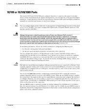
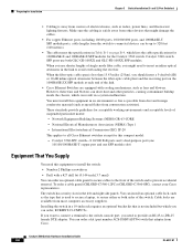
...ports, 10/100/1000 ports, and 1000BASE-T SFP module ports, cable lengths from the switch to connected devices can result in the left and right side panels. You can order a kit (part number ACS-DSBUASYN=) with that might need to insert an inline optical attenuator in an environment...-T copper port and one SFP module slot) Equipment That You Supply You need to provide an RJ-45-to all Cisco Ethernet switches except for the Catalyst 3560 switch. Catalyst 3560 Switch Hardware Installation Guide 3-6 OL-6337-07 You can order an optional cable guard to secure cables to 328 feet (100...
...ports, 10/100/1000 ports, and 1000BASE-T SFP module ports, cable lengths from the switch to connected devices can result in the left and right side panels. You can order a kit (part number ACS-DSBUASYN=) with that might need to insert an inline optical attenuator in an environment...-T copper port and one SFP module slot) Equipment That You Supply You need to provide an RJ-45-to all Cisco Ethernet switches except for the Catalyst 3560 switch. Catalyst 3560 Switch Hardware Installation Guide 3-6 OL-6337-07 You can order an optional cable guard to secure cables to 328 feet (100...