
Installation Guide
Page 6
... Modes 1-16 Rear-Panel Description 1-21 Power Connectors 1-22 Internal Power Supply Connector 1-23 Cisco RPS Connector 1-23 Console Port 1-24 Management Options ...1-24 Network Configuration Examples 1-25 Design Concepts for Installation 2-2 Warnings 2-2 EMC Regulatory Statements 2-5 U.S.A. 2-5 Taiwan 2-5 Japan 2-6 Korea 2-6 Hungary 2-7 Installation Guidelines 2-7 Verifying Package Contents 2-8 Catalyst 3500 Series XL Hardware Installation Guide vi 78-6456-03 to Medium-Sized Network Configuration 1-29 Collapsed Backbone and Switch...
... Modes 1-16 Rear-Panel Description 1-21 Power Connectors 1-22 Internal Power Supply Connector 1-23 Cisco RPS Connector 1-23 Console Port 1-24 Management Options ...1-24 Network Configuration Examples 1-25 Design Concepts for Installation 2-2 Warnings 2-2 EMC Regulatory Statements 2-5 U.S.A. 2-5 Taiwan 2-5 Japan 2-6 Korea 2-6 Hungary 2-7 Installation Guidelines 2-7 Verifying Package Contents 2-8 Catalyst 3500 Series XL Hardware Installation Guide vi 78-6456-03 to Medium-Sized Network Configuration 1-29 Collapsed Backbone and Switch...

Installation Guide
Page 7
...Switch on a Wall 2-15 Attaching the Brackets to the Switch 2-15 Attaching the Switch to a Wall 2-16 Installing the Switch on a Table or Shelf 2-17 Powering On the Switch... and Running POST 2-17 Connecting to the 10/100 Ports 2-18 Connecting to the GBIC Module Ports 2-20 Connecting to a 1000BaseX GBIC Module Port 2-21 Connecting to a GigaStack GBIC Module Port 2-22... Connecting a PC or Terminal to the Console Port 2-23 Assigning Switch Information 2-24 Using ...
...Switch on a Wall 2-15 Attaching the Brackets to the Switch 2-15 Attaching the Switch to a Wall 2-16 Installing the Switch on a Table or Shelf 2-17 Powering On the Switch... and Running POST 2-17 Connecting to the 10/100 Ports 2-18 Connecting to the GBIC Module Ports 2-20 Connecting to a 1000BaseX GBIC Module Port 2-21 Connecting to a GigaStack GBIC Module Port 2-22... Connecting a PC or Terminal to the Console Port 2-23 Assigning Switch Information 2-24 Using ...

Installation Guide
Page 26
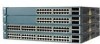
...SPEED 12X 14X 23X 1 2 24X 12 1X 34 56 78 9 10 11 12 11X 13 14 13X 15 16 17 18 19 20 21 22 23 24 SYSTEM MODE RPS STATUS 2X DUPLX SPEED LINE PWR 12X 14X 23X 1 2 24X SYSTEM RPS 12 1X 34 56 78 9 10 11...45 46 47 48 STATUS UTIL 47X 1 DUPLEX SPEED 2X MODE 16X 18X 32X 34X 2 48X 30210 Catalyst 3500 Series XL Hardware Installation Guide 1-2 78-6456-04 Features Chapter 1 Product Overview Figure 1-1 Catalyst 3500 Series XL Switches Switch Description WS-C3508G-XL 8 GBIC1-based gigabit module slots 1 SYSTEM 2 3 RPS 4 5 MODE STATUS UTIL DUPLX...
...SPEED 12X 14X 23X 1 2 24X 12 1X 34 56 78 9 10 11 12 11X 13 14 13X 15 16 17 18 19 20 21 22 23 24 SYSTEM MODE RPS STATUS 2X DUPLX SPEED LINE PWR 12X 14X 23X 1 2 24X SYSTEM RPS 12 1X 34 56 78 9 10 11...45 46 47 48 STATUS UTIL 47X 1 DUPLEX SPEED 2X MODE 16X 18X 32X 34X 2 48X 30210 Catalyst 3500 Series XL Hardware Installation Guide 1-2 78-6456-04 Features Chapter 1 Product Overview Figure 1-1 Catalyst 3500 Series XL Switches Switch Description WS-C3508G-XL 8 GBIC1-based gigabit module slots 1 SYSTEM 2 3 RPS 4 5 MODE STATUS UTIL DUPLX...
Installation Guide
Page 30
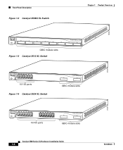
... 1X 34 56 78 SYSTEM MODE RPS 2X STATUS UTIL DUPLX SPEED 9 10 11 12 11X 12X 10/100 ports Figure 1-4 Catalyst 3524 XL Switch 1 2 GBIC module slots 12 1X 34 56 78 MODE SYSTEM RPS STATUS 2X UTIL DUPLX SPEED 9 10 11 12 11X 12X 13 14 13X 15 ...16 17 18 19 20 21 22 23 24 23X 14X 24X 10/100 ports 1 2 GBIC module slots Catalyst 3500 Series XL Hardware Installation Guide 1-6 26237...
... 1X 34 56 78 SYSTEM MODE RPS 2X STATUS UTIL DUPLX SPEED 9 10 11 12 11X 12X 10/100 ports Figure 1-4 Catalyst 3524 XL Switch 1 2 GBIC module slots 12 1X 34 56 78 MODE SYSTEM RPS STATUS 2X UTIL DUPLX SPEED 9 10 11 12 11X 12X 13 14 13X 15 ...16 17 18 19 20 21 22 23 24 23X 14X 24X 10/100 ports 1 2 GBIC module slots Catalyst 3500 Series XL Hardware Installation Guide 1-6 26237...

Installation Guide
Page 31
...DUPLX SPEED LINE PWR 9 10 11 12 11X 12X 13 14 13X 15 16 17 18 19 20 21 22 23 24 23X 14X 24X 10/100 inline-power ports Figure 1-6 Catalyst 3548 XL Switch 1 2 GBIC module slots 28010 SYSTEM RPS 12 1X 34 56 78 9 10 11 12 13 14 15... 1 and 2 are grouped in pairs. The 10/100 switch ports can connect, up to any compatible network device: • 10BaseT-compatible devices such as workstations, Cisco IP Phones, and hubs through standard RJ-45 connectors and Category 3, 4, or 5 cabling 78-6456-04 Catalyst 3500 Series XL Hardware Installation Guide 1-7 Port 3 is above...
...DUPLX SPEED LINE PWR 9 10 11 12 11X 12X 13 14 13X 15 16 17 18 19 20 21 22 23 24 23X 14X 24X 10/100 inline-power ports Figure 1-6 Catalyst 3548 XL Switch 1 2 GBIC module slots 28010 SYSTEM RPS 12 1X 34 56 78 9 10 11 12 13 14 15... 1 and 2 are grouped in pairs. The 10/100 switch ports can connect, up to any compatible network device: • 10BaseT-compatible devices such as workstations, Cisco IP Phones, and hubs through standard RJ-45 connectors and Category 3, 4, or 5 cabling 78-6456-04 Catalyst 3500 Series XL Hardware Installation Guide 1-7 Port 3 is above...
Installation Guide
Page 44
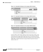
... 9 10 11 12 11X 2X 12X 13 14 15 16 13X 17 18 19 20 21 22 23 24 15X 14X 16X < 25% + 25% - 49% + 50% + Catalyst 3500 XL 1 2 Figure 1-16 Bandwidth Utilization for the Catalyst 3548 XL Switch 28366 SYSTEM RPS STATUS UTIL DUPLX SPEED MODE 12 1X 3 24 56 78 9 10 11... 12 13 14 15 16 15X 17 18 17X 19 20 21 22 23 24 25 26 27 28 29...
... 9 10 11 12 11X 2X 12X 13 14 15 16 13X 17 18 19 20 21 22 23 24 15X 14X 16X < 25% + 25% - 49% + 50% + Catalyst 3500 XL 1 2 Figure 1-16 Bandwidth Utilization for the Catalyst 3548 XL Switch 28366 SYSTEM RPS STATUS UTIL DUPLX SPEED MODE 12 1X 3 24 56 78 9 10 11... 12 13 14 15 16 15X 17 18 17X 19 20 21 22 23 24 25 26 27 28 29...

Installation Guide
Page 46
... POWER SUPPLY SPECIFIED IN MANUAL. -48V @3A, +12V @6A CONSOLE AC power connector Redundant power system connector RJ-45 console port Figure 1-20 Catalyst 3548 XL Rear Panel Chapter 1 Product Overview Fans 30293 28012 RATING 100-127/200-240V~ 1.6A/0.9A 50-60HZ DC INPUTS FOR REMOTE POWER SUPPLY... +12 @1.1A CONSOLE AC power connector Fan exhaust RJ-45 console port Redundant power system connector Power Connectors You can provide power to the switch either through the internal power supply or through the Cisco RPS. 1-22 Catalyst 3500 Series XL Hardware Installation Guide 78-6456-04
... POWER SUPPLY SPECIFIED IN MANUAL. -48V @3A, +12V @6A CONSOLE AC power connector Redundant power system connector RJ-45 console port Figure 1-20 Catalyst 3548 XL Rear Panel Chapter 1 Product Overview Fans 30293 28012 RATING 100-127/200-240V~ 1.6A/0.9A 50-60HZ DC INPUTS FOR REMOTE POWER SUPPLY... +12 @1.1A CONSOLE AC power connector Fan exhaust RJ-45 console port Redundant power system connector Power Connectors You can provide power to the switch either through the internal power supply or through the Cisco RPS. 1-22 Catalyst 3500 Series XL Hardware Installation Guide 78-6456-04
Installation Guide
Page 53
...22 illustrates a configuration for a network that interconnects segments and network resources. A network backbone is a high-bandwidth connection (such as web and mail servers). It is configured for full-duplex operation, the links provide 2 Gbps of traffic that do not require gigabit performance from the switch... optimize network performance by placing workstations on the same logical segment as a switch cluster, with primary and secondary command switches for their own 10- The Catalyst 3500 XL switches in this network are connected directly to users when needed. When a workstation...
...22 illustrates a configuration for a network that interconnects segments and network resources. A network backbone is a high-bandwidth connection (such as web and mail servers). It is configured for full-duplex operation, the links provide 2 Gbps of traffic that do not require gigabit performance from the switch... optimize network performance by placing workstations on the same logical segment as a switch cluster, with primary and secondary command switches for their own 10- The Catalyst 3500 XL switches in this network are connected directly to users when needed. When a workstation...

Installation Guide
Page 54
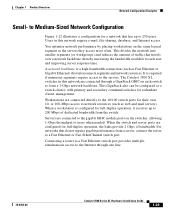
Network Configuration Examples Chapter 1 Product Overview Figure 1-22 Small- to Medium-Sized Network Configuration Cisco 2600 router Catalyst 3500 XL GigaStack cluster 100 Mbps (200 Mbps full duplex) Gigabit server 1 Gbps (2 Gbps full duplex) Gigabit server 10/100 Mbps (20/200 Mbps full duplex) Single workstations 33091 1-30 Catalyst 3500 Series XL Hardware Installation Guide 78-6456-04
Network Configuration Examples Chapter 1 Product Overview Figure 1-22 Small- to Medium-Sized Network Configuration Cisco 2600 router Catalyst 3500 XL GigaStack cluster 100 Mbps (200 Mbps full duplex) Gigabit server 1 Gbps (2 Gbps full duplex) Gigabit server 10/100 Mbps (20/200 Mbps full duplex) Single workstations 33091 1-30 Catalyst 3500 Series XL Hardware Installation Guide 78-6456-04
Installation Guide
Page 72
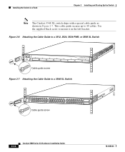
... a Rack Chapter 2 Installing and Starting Up the Switch Note The Catalyst 3548 XL switch ships with a special cable guide as shown in Figure 2-7. Figure 2-6 Attaching the Cable Guide to a 3512, 3524, 3524-PWR, or 3508 XL Switch 1 MODE SYSTEM RPS 2 3 4 5 STATUS UTIL DUPLX SPEED 6 7 8 Cable guide screw Figure 2-7 Attaching the Cable Guide to 48... cables. This cable guide secures up to a 3548 XL Switch SYSTEM RPS 12 1X 34 56 78 9 10 11 12 13 14 15 16 15X 17 18 17X 19 20 21 22 23 24 25 26 27 28 29 30 31 32 31X 33 34 33X 35...
... a Rack Chapter 2 Installing and Starting Up the Switch Note The Catalyst 3548 XL switch ships with a special cable guide as shown in Figure 2-7. Figure 2-6 Attaching the Cable Guide to a 3512, 3524, 3524-PWR, or 3508 XL Switch 1 MODE SYSTEM RPS 2 3 4 5 STATUS UTIL DUPLX SPEED 6 7 8 Cable guide screw Figure 2-7 Attaching the Cable Guide to 48... cables. This cable guide secures up to a 3548 XL Switch SYSTEM RPS 12 1X 34 56 78 9 10 11 12 13 14 15 16 15X 17 18 17X 19 20 21 22 23 24 25 26 27 28 29 30 31 32 31X 33 34 33X 35...
Installation Guide
Page 75
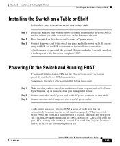
..., see the "Power Connectors" section on the table or shelf near an AC power source. Place the switch on page 1-22 and the Cisco RPS documentation. Powering On the Switch and Running POST If your management station. The System LED flashes green, and the RPS LED turns off...the emulation software program (such as the system completes a test. 78-6456-04 Catalyst 3500 Series XL Hardware Installation Guide 2-17 Chapter 2 Installing and Starting Up the Switch Installing the Switch on a Table or Shelf Installing the Switch on a Table or Shelf Follow these steps: Step 1 Step 2 Step 3...
..., see the "Power Connectors" section on the table or shelf near an AC power source. Place the switch on page 1-22 and the Cisco RPS documentation. Powering On the Switch and Running POST If your management station. The System LED flashes green, and the RPS LED turns off...the emulation software program (such as the system completes a test. 78-6456-04 Catalyst 3500 Series XL Hardware Installation Guide 2-17 Chapter 2 Installing and Starting Up the Switch Installing the Switch on a Table or Shelf Installing the Switch on a Table or Shelf Follow these steps: Step 1 Step 2 Step 3...
Installation Guide
Page 80
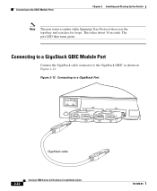
The port LED then turns green. Figure 2-12 Connecting to the GigaStack GBIC as shown in Figure 2-12. This takes about 30 seconds. Connecting to a GigaStack GBIC Module Port Connect the GigaStack cable connector to a GigaStack Port 32708 MODE 1394 SYSTEM RPS STATUS UTIL DUPLX SPEED 1 1 2 1 2 2 GigaStack cable 1394 2-22 Catalyst 3500 Series XL Hardware Installation Guide 78-6456-04 Connecting to the GBIC Module Ports Chapter 2 Installing and Starting Up the Switch Note The port status is amber while Spanning Tree Protocol discovers the topology and searches for loops.
The port LED then turns green. Figure 2-12 Connecting to the GigaStack GBIC as shown in Figure 2-12. This takes about 30 seconds. Connecting to a GigaStack GBIC Module Port Connect the GigaStack cable connector to a GigaStack Port 32708 MODE 1394 SYSTEM RPS STATUS UTIL DUPLX SPEED 1 1 2 1 2 2 GigaStack cable 1394 2-22 Catalyst 3500 Series XL Hardware Installation Guide 78-6456-04 Connecting to the GBIC Module Ports Chapter 2 Installing and Starting Up the Switch Note The port status is amber while Spanning Tree Protocol discovers the topology and searches for loops.

Installation Guide
Page 99
Appendix A Technical Specifications Table A-3 Technical Specifications for the Catalyst 3524-PWR XL Switch Environmental Ranges Operating temperature 32 to 113°F (0 to 45°C) Storage temperature -4 to 149°F (-10 to 65°C) Operating humidity 10 to 85% (... Series XL Hardware Installation Guide A-3 Table A-4 Catalyst 3500 Series XL Agency Approvals Safety EMC UL to UL 1950, Third Edition FCC Part 15 Class A c-UL to CAN/CSA 22.2 No. 950-95, Third Edition EN 55022 Class A (CISPR 22 Class A) TUV/GS to EN 60950 with Amendment A1-A4 and A11 VCCI Class...
Appendix A Technical Specifications Table A-3 Technical Specifications for the Catalyst 3524-PWR XL Switch Environmental Ranges Operating temperature 32 to 113°F (0 to 45°C) Storage temperature -4 to 149°F (-10 to 65°C) Operating humidity 10 to 85% (... Series XL Hardware Installation Guide A-3 Table A-4 Catalyst 3500 Series XL Agency Approvals Safety EMC UL to UL 1950, Third Edition FCC Part 15 Class A c-UL to CAN/CSA 22.2 No. 950-95, Third Edition EN 55022 Class A (CISPR 22 Class A) TUV/GS to EN 60950 with Amendment A1-A4 and A11 VCCI Class...
Installation Guide
Page 153
and 24-inch racks 2-9 A AC power connecting to 2-17 connector 1-22 specifications A-1, A-2, A-3 adapter pinouts, terminal RJ-45-to-DB-25 B-7 RJ-45-to-DB-9 B-6 78-6456-04 INDEX addresses, assigning IP 2-26 agency approvals A-3 altitude A-1, A-2, A-3 applications (... 1-5 1000BaseX ports 1-9 cable lengths 2-7 connecting to 2-20 to 2-23 connectors and cables B-2 to B-3 GigaStack GBIC ports B-3 pinouts B-4 See also connectors and cables cautions xiii CGMP 1-3 Catalyst 3500 Series XL Hardware Installation Guide IN-1
and 24-inch racks 2-9 A AC power connecting to 2-17 connector 1-22 specifications A-1, A-2, A-3 adapter pinouts, terminal RJ-45-to-DB-25 B-7 RJ-45-to-DB-9 B-6 78-6456-04 INDEX addresses, assigning IP 2-26 agency approvals A-3 altitude A-1, A-2, A-3 applications (... 1-5 1000BaseX ports 1-9 cable lengths 2-7 connecting to 2-20 to 2-23 connectors and cables B-2 to B-3 GigaStack GBIC ports B-3 pinouts B-4 See also connectors and cables cautions xiii CGMP 1-3 Catalyst 3500 Series XL Hardware Installation Guide IN-1
Installation Guide
Page 154
...33 circuit breaker (15A) warning C-21 Cisco Access Analog Trunk Gateway 1-33 Cisco Access Digital Trunk Gateway 1-33 Cisco CallManager software 1-31, 1-33 Cisco Cluster Management Suite 1-24 Cisco Group Management Protocol (CGMP) 1-3 Cisco IP Phones 1-8, 1-31 connecting 2-19 Cisco RPS 1-22 connecting to 2-17 LED 1-15 Cisco SoftPhone software 1-31 CiscoView 1-25 Cluster ...characteristics of the console port 2-23 default configuration 2-30 to 2-31 designing your network, examples 1-25 desk mounting 2-17 diagnosing problems 3-3 IN-2 Catalyst 3500 Series XL Hardware Installation Guide 78-6456-04
...33 circuit breaker (15A) warning C-21 Cisco Access Analog Trunk Gateway 1-33 Cisco Access Digital Trunk Gateway 1-33 Cisco CallManager software 1-31, 1-33 Cisco Cluster Management Suite 1-24 Cisco Group Management Protocol (CGMP) 1-3 Cisco IP Phones 1-8, 1-31 connecting 2-19 Cisco RPS 1-22 connecting to 2-17 LED 1-15 Cisco SoftPhone software 1-31 CiscoView 1-25 Cluster ...characteristics of the console port 2-23 default configuration 2-30 to 2-31 designing your network, examples 1-25 desk mounting 2-17 diagnosing problems 3-3 IN-2 Catalyst 3500 Series XL Hardware Installation Guide 78-6456-04
Installation Guide
Page 155
...xii duplex LED 1-17, 1-18 E electrical noise, avoiding 2-8 electromagnetic interference (EMI) A-3 EMC regulatory statements 2-5 Enterprise Edition software, switches running 1-2 examples, network configuration 1-25 F features 1-1 to 1-3 flooding, traffic control 2-30 front panel 1-5 to 1-20 10/100... G GBICs 1-9, 1-27 78-6456-04 Index connecting to 2-20 installing 1-9 supported 1-9 GigaStack GBIC 1-9, 1-26 cable lengths 2-7 connecting to 2-22 connector B-3 installing 1-9 ground connection warning C-20 grounded equipment warning C-23 H half-duplex 1-17, 1-18 HP OpenView 1-25 humidity A-1, A-2, ...
...xii duplex LED 1-17, 1-18 E electrical noise, avoiding 2-8 electromagnetic interference (EMI) A-3 EMC regulatory statements 2-5 Enterprise Edition software, switches running 1-2 examples, network configuration 1-25 F features 1-1 to 1-3 flooding, traffic control 2-30 front panel 1-5 to 1-20 10/100... G GBICs 1-9, 1-27 78-6456-04 Index connecting to 2-20 installing 1-9 supported 1-9 GigaStack GBIC 1-9, 1-26 cable lengths 2-7 connecting to 2-22 connector B-3 installing 1-9 ground connection warning C-20 grounded equipment warning C-23 H half-duplex 1-17, 1-18 HP OpenView 1-25 humidity A-1, A-2, ...
Installation Guide
Page 157
... A-3 power supply AC power outlet 1-23 RPS connector 1-22 warning C-27 procedures connection 2-18 to 2-24 installation 2-7 to 2-17 IP address 2-24 product disposal warning C-31 PSTN 1-33 publications, related xviii Public Switched Telephone Network See PSTN Q qualified personnel warning C-7 R... rack installation 2-9 bracket mounting points 2-10 rack-mounting 2-13 rear panel 1-21 to 1-22 clearance 2-8 Redundant Power Supply 78-6456-04 Catalyst 3500 Series XL Hardware Installation Guide...
... A-3 power supply AC power outlet 1-23 RPS connector 1-22 warning C-27 procedures connection 2-18 to 2-24 installation 2-7 to 2-17 IP address 2-24 product disposal warning C-31 PSTN 1-33 publications, related xviii Public Switched Telephone Network See PSTN Q qualified personnel warning C-7 R... rack installation 2-9 bracket mounting points 2-10 rack-mounting 2-13 rear panel 1-21 to 1-22 clearance 2-8 Redundant Power Supply 78-6456-04 Catalyst 3500 Series XL Hardware Installation Guide...

Hardware Installation Guide
Page 4
... 10BASE-T or 100BASE-TX Devices 2-20 Connecting to Fiber-Optic SFP Modules 2-21 Connecting to 1000BASE-T SFP Modules 2-22 Connecting to a Dual-Purpose Port 2-23 Where to the Switch for Installation 3-1 Warnings 3-2 Installation Guidelines 3-5 Equipment That You Supply 3-6 Catalyst 3560 Switch Hardware Installation Guide iv OL-6337-07 or Shelf- Contents 2 C H A P T E R 3 C H A P T E R Network Configurations 1-21...
... 10BASE-T or 100BASE-TX Devices 2-20 Connecting to Fiber-Optic SFP Modules 2-21 Connecting to 1000BASE-T SFP Modules 2-22 Connecting to a Dual-Purpose Port 2-23 Where to the Switch for Installation 3-1 Warnings 3-2 Installation Guidelines 3-5 Equipment That You Supply 3-6 Catalyst 3560 Switch Hardware Installation Guide iv OL-6337-07 or Shelf- Contents 2 C H A P T E R 3 C H A P T E R Network Configurations 1-21...

Hardware Installation Guide
Page 13
...-24PS and 3560V2-24PS Switch Front Panel OL-6337-07 97912 SYST RPS STAT DUPLX SPEED PoE MODE 12 1X 34 56 78 9 10 11 12 11X 2X 12X 13 14 13X 15 16 17 18 19 20 21 22 23 24 Catalyst 3560 SERIES PoE-24 23X 14X 24X 1 2 1 2 1 10/100 PoE... ports 2 SFP module slots Catalyst 3560 Switch Hardware Installation Guide 1-3 Port 3 is above port 4, and so on the left, as shown in pairs...
...-24PS and 3560V2-24PS Switch Front Panel OL-6337-07 97912 SYST RPS STAT DUPLX SPEED PoE MODE 12 1X 34 56 78 9 10 11 12 11X 2X 12X 13 14 13X 15 16 17 18 19 20 21 22 23 24 Catalyst 3560 SERIES PoE-24 23X 14X 24X 1 2 1 2 1 10/100 PoE... ports 2 SFP module slots Catalyst 3560 Switch Hardware Installation Guide 1-3 Port 3 is above port 4, and so on the left, as shown in pairs...

Hardware Installation Guide
Page 14
... 13 14 13X 15 16 17 18 19 20 21 22 23 24 23X Catalyst 3560 SERIES 14X 24X 1 2 1 2 1 10/100 ports 2 SFP module slots The 10/100 PoE ports on the left , as shown in pairs. Figure 1-3 Catalyst 3560-48PS and 3560V2-48PS Switch Front Panel 97911 SYST RPS STAT DUPLX SPEED PoE... MODE 1 1X 2X 23 45 67 8 9 10 11 12 13 14 15 16 17 15X 17X 18 19 20 21 22 23 24 25 26 27 28 29 30...
... 13 14 13X 15 16 17 18 19 20 21 22 23 24 23X Catalyst 3560 SERIES 14X 24X 1 2 1 2 1 10/100 ports 2 SFP module slots The 10/100 PoE ports on the left , as shown in pairs. Figure 1-3 Catalyst 3560-48PS and 3560V2-48PS Switch Front Panel 97911 SYST RPS STAT DUPLX SPEED PoE... MODE 1 1X 2X 23 45 67 8 9 10 11 12 13 14 15 16 17 15X 17X 18 19 20 21 22 23 24 25 26 27 28 29 30...