
Installation Guide
Page 6
... P T E R LEDs 1-11 System LED 1-14 RPS LED 1-15 Port LEDs and Modes 1-16 Rear-Panel Description 1-21 Power Connectors 1-22 Internal Power Supply Connector 1-23 Cisco RPS Connector 1-23 Console Port 1-24 Management Options 1-24 Network Configuration Examples 1-25 Design Concepts for Installation 2-2 Warnings 2-2 EMC Regulatory Statements 2-5 U.S.A. 2-5 Taiwan 2-5 Japan 2-6 Korea 2-6 Hungary 2-7 Installation Guidelines 2-7 Verifying Package Contents 2-8 Catalyst 3500 Series XL Hardware Installation Guide vi 78-6456-03 to Medium-Sized Network Configuration 1-29 Collapsed Backbone and Switch...
... P T E R LEDs 1-11 System LED 1-14 RPS LED 1-15 Port LEDs and Modes 1-16 Rear-Panel Description 1-21 Power Connectors 1-22 Internal Power Supply Connector 1-23 Cisco RPS Connector 1-23 Console Port 1-24 Management Options 1-24 Network Configuration Examples 1-25 Design Concepts for Installation 2-2 Warnings 2-2 EMC Regulatory Statements 2-5 U.S.A. 2-5 Taiwan 2-5 Japan 2-6 Korea 2-6 Hungary 2-7 Installation Guidelines 2-7 Verifying Package Contents 2-8 Catalyst 3500 Series XL Hardware Installation Guide vi 78-6456-03 to Medium-Sized Network Configuration 1-29 Collapsed Backbone and Switch...

Installation Guide
Page 12
..., such as passwords or tabs, are installing the switch. Chapter 3, "Troubleshooting," describes how to the switch. Appendix A, "Technical Specifications," lists the physical and environmental specifications for installing a switch on a rack, wall, table, or shelf. Catalyst 3500 Series XL Hardware Installation Guide xii 78-6456-04 Organization Preface Organization This guide is organized into the following conventions to set up the switch initial configuration. It describes the switch ports, the standards they support, and the switch LEDs.
..., such as passwords or tabs, are installing the switch. Chapter 3, "Troubleshooting," describes how to the switch. Appendix A, "Technical Specifications," lists the physical and environmental specifications for installing a switch on a rack, wall, table, or shelf. Catalyst 3500 Series XL Hardware Installation Guide xii 78-6456-04 Organization Preface Organization This guide is organized into the following conventions to set up the switch initial configuration. It describes the switch ports, the standards they support, and the switch LEDs.

Installation Guide
Page 27
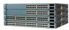
... IP multicast traffic • Broadcast storm control to prevent performance degradation from broadcast storms • Switch Port Analyzer (SPAN) port monitoring on AC input and supplies DC output to four 1000BaseZX GBICs with the Catalyst 3508G XL switch) Management • Cisco IOS command-line interface (CLI) through the console port or Telnet • CiscoView device-management application • Cluster Management Suite, a web-based tool for managing switch clusters or an individual switch through a single IP address • Simple Network Management Protocol (SNMP) Power...
... IP multicast traffic • Broadcast storm control to prevent performance degradation from broadcast storms • Switch Port Analyzer (SPAN) port monitoring on AC input and supplies DC output to four 1000BaseZX GBICs with the Catalyst 3508G XL switch) Management • Cisco IOS command-line interface (CLI) through the console port or Telnet • CiscoView device-management application • Cluster Management Suite, a web-based tool for managing switch clusters or an individual switch through a single IP address • Simple Network Management Protocol (SNMP) Power...

Installation Guide
Page 28
... VLANs • ISL and IEEE 802.1Q trunking support on all ports • Support for voice VLAN ID (VVID) • High-speed EtherChannel connections between switches and servers • 8192 MAC addresses • IEEE 802.1p capable • CGMP to limit the flooding of IP multicast traffic • Broadcast storm control to prevent performance degradation from broadcast storms • SPAN port monitoring on any port • Support for command switch redundancy • Support for Cisco GBIC modules...
... VLANs • ISL and IEEE 802.1Q trunking support on all ports • Support for voice VLAN ID (VVID) • High-speed EtherChannel connections between switches and servers • 8192 MAC addresses • IEEE 802.1p capable • CGMP to limit the flooding of IP multicast traffic • Broadcast storm control to prevent performance degradation from broadcast storms • SPAN port monitoring on any port • Support for command switch redundancy • Support for Cisco GBIC modules...

Installation Guide
Page 29
... (continued) Management • Cisco IOS CLI through the console port or Telnet • CiscoView device-management application • Cluster Management Suite, a web-based tool for managing switch clusters or an individual switch through a single IP address • SNMP Power Redundancy • Connection for optional Cisco RPS 600 that operates on AC input and supplies DC output to the Catalyst 3512, 3524, and 3548 XL switches • Connection for optional Cisco RPS 300...
... (continued) Management • Cisco IOS CLI through the console port or Telnet • CiscoView device-management application • Cluster Management Suite, a web-based tool for managing switch clusters or an individual switch through a single IP address • SNMP Power Redundancy • Connection for optional Cisco RPS 600 that operates on AC input and supplies DC output to the Catalyst 3512, 3524, and 3548 XL switches • Connection for optional Cisco RPS 300...

Installation Guide
Page 32
... B, "Connector and Cable Specifications." When you can sense the speed and duplex settings of half duplex, full duplex, 10 Mbps, or 100 Mbps. When connecting the switch to the Cisco IOS Desktop Switching Software Configuration Guide for more information about these cables do not work for inline power on a port, the port Catalyst 3500 Series XL Hardware Installation Guide 1-8 78-6456-04 If the connected device also supports autonegotiation, the switch port negotiates the best connection (that is required...
... B, "Connector and Cable Specifications." When you can sense the speed and duplex settings of half duplex, full duplex, 10 Mbps, or 100 Mbps. When connecting the switch to the Cisco IOS Desktop Switching Software Configuration Guide for more information about these cables do not work for inline power on a port, the port Catalyst 3500 Series XL Hardware Installation Guide 1-8 78-6456-04 If the connected device also supports autonegotiation, the switch port negotiates the best connection (that is required...

Installation Guide
Page 33
... AC power source for creating a 1-Gbps stack configuration of up to nine half-duplex links (in a point-to-point configuration) or up to nine Catalyst 3500 XL switches. If the primary source fails, the second power source becomes the primary power source to other Gigabit Ethernet devices. The power source to which the Cisco IP Phone is first connected becomes its backup. Using the required Cisco proprietary signaling and cabling, the...
... AC power source for creating a 1-Gbps stack configuration of up to nine half-duplex links (in a point-to-point configuration) or up to nine Catalyst 3500 XL switches. If the primary source fails, the second power source becomes the primary power source to other Gigabit Ethernet devices. The power source to which the Cisco IP Phone is first connected becomes its backup. Using the required Cisco proprietary signaling and cabling, the...

Installation Guide
Page 39
... Hardware Installation Guide 1-15 RPS is not a recommended configuration. The switch goes through its normal boot sequence when it restarts. Table 1-4 and Table 1-5 list the LED colors and their meanings. One of the RPS shows the revision level. The label on . Chapter 1 Product Overview Front-Panel Description RPS LED The Redundant Power System (RPS) LED shows the RPS status. RPS and the switch AC power supply are using power...
... Hardware Installation Guide 1-15 RPS is not a recommended configuration. The switch goes through its normal boot sequence when it restarts. Table 1-4 and Table 1-5 list the LED colors and their meanings. One of the RPS shows the revision level. The label on . Chapter 1 Product Overview Front-Panel Description RPS LED The Redundant Power System (RPS) LED shows the RPS status. RPS and the switch AC power supply are using power...

Installation Guide
Page 40
... is lost. Internal power supply of information displayed through the port LEDs. Port LEDs and Modes Each 10/100 port and module slot has a port LED. RPS is backing up another switch in the RPS could be powered down , and redundancy is connected and operational. The port modes (Table 1-6) determine the type of the switch is down , or a fan on the RPS. When you change the port mode in use by the switch. 1-16 Catalyst 3500 Series XL Hardware Installation Guide...
... is lost. Internal power supply of information displayed through the port LEDs. Port LEDs and Modes Each 10/100 port and module slot has a port LED. RPS is backing up another switch in the RPS could be powered down , and redundancy is connected and operational. The port modes (Table 1-6) determine the type of the switch is down , or a fan on the RPS. When you change the port mode in use by the switch. 1-16 Catalyst 3500 Series XL Hardware Installation Guide...

Installation Guide
Page 41
... data. If the right-most LED is amber, the switch is reconfigured, the port LED can affect connectivity, and errors such as STP checks the switch for details. Port is operating in half duplex. Chapter 1 Product Overview Front-Panel Description Table 1-6 Port Mode LEDs (continued) Mode LED DUPLX SPEED LINE PWR Port Mode Port duplex mode Port speed Port inline power Description The port duplex mode: full duplex or half duplex. Link present. Port was disabled by management or an address violation or was blocked by Spanning Tree Protocol (STP). Note After a port is using...
... data. If the right-most LED is amber, the switch is reconfigured, the port LED can affect connectivity, and errors such as STP checks the switch for details. Port is operating in half duplex. Chapter 1 Product Overview Front-Panel Description Table 1-6 Port Mode LEDs (continued) Mode LED DUPLX SPEED LINE PWR Port Mode Port duplex mode Port speed Port inline power Description The port duplex mode: full duplex or half duplex. Link present. Port was disabled by management or an address violation or was blocked by Spanning Tree Protocol (STP). Note After a port is using...
Installation Guide
Page 49
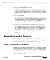
... switch supports a comprehensive set configuration parameters and to access the CLI. Table 1-9 describes what can cause network performance to degrade and describes how you can configure your network users and the relative priority of the network applications they use to set of MIB extensions and MIB II, the IEEE 802.1D bridge MIB, and four Remote Monitoring (RMON) groups. Chapter 1 Product Overview Network Configuration Examples • Cisco IOS command-line interface (CLI) Connect a PC or terminal...
... switch supports a comprehensive set configuration parameters and to access the CLI. Table 1-9 describes what can cause network performance to degrade and describes how you can configure your network users and the relative priority of the network applications they use to set of MIB extensions and MIB II, the IEEE 802.1D bridge MIB, and four Remote Monitoring (RMON) groups. Chapter 1 Product Overview Network Configuration Examples • Cisco IOS command-line interface (CLI) Connect a PC or terminal...

Installation Guide
Page 50
... attached files) and from bandwidth-intensive applications (such as multimedia) • Connect global resources-such as servers and routers to which network users require equal access-directly to the Fast Ethernet or Gigabit Ethernet switch ports so that they have their own Fast Ethernet or Gigabit Ethernet segment. • Use the Fast EtherChannel or Gigabit EtherChannel feature between Catalyst 4908G-L3 switches. Use switches that support at least two queues per port to prioritize voice and data traffic...
... attached files) and from bandwidth-intensive applications (such as multimedia) • Connect global resources-such as servers and routers to which network users require equal access-directly to the Fast Ethernet or Gigabit Ethernet switch ports so that they have their own Fast Ethernet or Gigabit Ethernet segment. • Use the Fast EtherChannel or Gigabit EtherChannel feature between Catalyst 4908G-L3 switches. Use switches that support at least two queues per port to prioritize voice and data traffic...

Installation Guide
Page 55
... secondary command switches, regardless of the geographic location of inter-VLAN routing and allows the router to the Cisco IP Phone. Using Cisco IP Phones, Cisco CallManager software, and Cisco SoftPhone software integrates telephony and IP networks, where the IP network supports both voice and data. You can use a Catalyst 4908G-L3 switch, as security and easier maintenance. Users with RJ-45 connectors-to the 10/100 inline-power ports on the Catalyst...
... secondary command switches, regardless of the geographic location of inter-VLAN routing and allows the router to the Cisco IP Phone. Using Cisco IP Phones, Cisco CallManager software, and Cisco SoftPhone software integrates telephony and IP networks, where the IP network supports both voice and data. You can use a Catalyst 4908G-L3 switch, as security and easier maintenance. Users with RJ-45 connectors-to the 10/100 inline-power ports on the Catalyst...
Installation Guide
Page 59
...; Installation procedures • Power-on self-test (POST) that ensures proper operation. CH A P T E R 2 Installing and Starting Up the Switch This chapter describes how to install and start up your Catalyst 3500 XL switches and to interpret the power-on procedures • Connection procedures • Set up procedures for initial configuration • Default configuration settings • Where to go next 78-6456-04 Catalyst 3500 Series XL Hardware Installation Guide...
...; Installation procedures • Power-on self-test (POST) that ensures proper operation. CH A P T E R 2 Installing and Starting Up the Switch This chapter describes how to install and start up your Catalyst 3500 XL switches and to interpret the power-on procedures • Connection procedures • Set up procedures for initial configuration • Default configuration settings • Where to go next 78-6456-04 Catalyst 3500 Series XL Hardware Installation Guide...

Installation Guide
Page 81
... support VT100 terminal emulation. For console port and adapter pinout information, see the "Cable and Adapter Specifications" section on the GigaStack GBIC connections and configuration scenarios, see the Catalyst GigaStack Gigabit Interface Converter Hardware Installation Guide. You can change the port baud rate. Chapter 2 Installing and Starting Up the Switch Connecting a PC or Terminal to the Console Port For more information on page B-4. Connecting a PC or Terminal to the Console Port Use the supplied rollover cable and DB-9 adapter to connect a PC to the switch console port...
... support VT100 terminal emulation. For console port and adapter pinout information, see the "Cable and Adapter Specifications" section on the GigaStack GBIC connections and configuration scenarios, see the Catalyst GigaStack Gigabit Interface Converter Hardware Installation Guide. You can change the port baud rate. Chapter 2 Installing and Starting Up the Switch Connecting a PC or Terminal to the Console Port For more information on page B-4. Connecting a PC or Terminal to the Console Port Use the supplied rollover cable and DB-9 adapter to connect a PC to the switch console port...
Installation Guide
Page 83
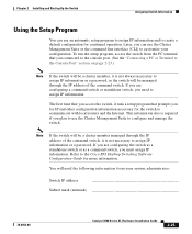
... setup program, access the switch from your configuration. Refer to create a default configuration for more information. Chapter 2 Installing and Starting Up the Switch Assigning Switch Information Using the Setup Program You can use the Cluster Management Suite or the command-line interface (CLI) to assign IP information or a password. You will be a cluster member managed through the IP address of the command switch, it is not always necessary to assign IP information or a password, as a command switch...
... setup program, access the switch from your configuration. Refer to create a default configuration for more information. Chapter 2 Installing and Starting Up the Switch Assigning Switch Information Using the Setup Program You can use the Cluster Management Suite or the command-line interface (CLI) to assign IP information or a password. You will be a cluster member managed through the IP address of the command switch, it is not always necessary to assign IP information or a password, as a command switch...
Installation Guide
Page 87
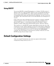
... physical MAC address. A database with the default configuration settings shown in the database. The switch must be stored in Table 2-1. 78-6456-04 Catalyst 3500 Series XL Hardware Installation Guide 2-29 To save the IP information, log in Flash memory is set up on the BOOTP server. Chapter 2 Installing and Starting Up the Switch Default Configuration Settings Using BOOTP You can use BOOTP to assign IP information to the CLI, and enter the write memory command...
... physical MAC address. A database with the default configuration settings shown in the database. The switch must be stored in Table 2-1. 78-6456-04 Catalyst 3500 Series XL Hardware Installation Guide 2-29 To save the IP information, log in Flash memory is set up on the BOOTP server. Chapter 2 Installing and Starting Up the Switch Default Configuration Settings Using BOOTP You can use BOOTP to assign IP information to the CLI, and enter the write memory command...

Installation Guide
Page 91
...), or the documentation that came with your SNMP application for troubleshooting problems: • Understanding POST results • Diagnosing problems 78-6456-04 Catalyst 3500 Series XL Hardware Installation Guide 3-1 CH A P T E R 3 Troubleshooting The LEDs on self-test (POST), port-connectivity problems, and overall switch performance. For a full description of the switch LEDs, see the "LEDs" section on page 1-11. You can also get statistics from the browser interface, from the command-line interface (CLI), or...
...), or the documentation that came with your SNMP application for troubleshooting problems: • Understanding POST results • Diagnosing problems 78-6456-04 Catalyst 3500 Series XL Hardware Installation Guide 3-1 CH A P T E R 3 Troubleshooting The LEDs on self-test (POST), port-connectivity problems, and overall switch performance. For a full description of the switch LEDs, see the "LEDs" section on page 1-11. You can also get statistics from the browser interface, from the command-line interface (CLI), or...

Installation Guide
Page 96
.... Catalyst 3500 Series XL Hardware Installation Guide 3-6 78-6456-04 Diagnosing Problems Chapter 3 Troubleshooting Table 3-2 Common Problems and Their Solutions (continued) Symptom System LED is overheating. • Nonfatal or fatal POST error detected. Replace the switch at your convenience. • Use the show env command to 45°C). - Make sure fan intake and exhaust areas are clear. Cisco IP Phone fails to see which POST test failed. If a multiple-fan failure is connected...
.... Catalyst 3500 Series XL Hardware Installation Guide 3-6 78-6456-04 Diagnosing Problems Chapter 3 Troubleshooting Table 3-2 Common Problems and Their Solutions (continued) Symptom System LED is overheating. • Nonfatal or fatal POST error detected. Replace the switch at your convenience. • Use the show env command to 45°C). - Make sure fan intake and exhaust areas are clear. Cisco IP Phone fails to see which POST test failed. If a multiple-fan failure is connected...
Installation Guide
Page 154
... LED 1-15 Cisco SoftPhone software 1-31 CiscoView 1-25 Cluster Builder application 1-24 Cluster Management Suite 1-24 Cluster Manager application 1-24 Cluster View application 1-24 command-line interface (CLI) 1-25 configuration, default values 2-30 configuration examples, network 1-25 connecting to 10/100 ports 2-18 to 1000BaseX ports 2-20 to console port 2-18, B-3 to GBICs 2-21 to GigaStack GBICs 2-22 connection procedures 2-18 to 2-24 connectivity problems, solving 3-3 connectors and cables 10/100 ports B-1 to B-2 1000BaseX ports B-2 to B-3 console port...
... LED 1-15 Cisco SoftPhone software 1-31 CiscoView 1-25 Cluster Builder application 1-24 Cluster Management Suite 1-24 Cluster Manager application 1-24 Cluster View application 1-24 command-line interface (CLI) 1-25 configuration, default values 2-30 configuration examples, network 1-25 connecting to 10/100 ports 2-18 to 1000BaseX ports 2-20 to console port 2-18, B-3 to GBICs 2-21 to GigaStack GBICs 2-22 connection procedures 2-18 to 2-24 connectivity problems, solving 3-3 connectors and cables 10/100 ports B-1 to B-2 1000BaseX ports B-2 to B-3 console port...


