
Hardware Installation Guide
Page 3
... 1-1 Front Panel Description 1-3 Fast Ethernet Switch Front Panel Descriptions 1-3 Gigabit Ethernet Switch Front Panel Descriptions 1-6 10/100 and 10/100/1000 Ports 1-8 PoE Ports 1-9 SFP Module Slots 1-10 SFP Modules 1-10 SFP Module Patch Cable 1-10 Dual-Purpose Port 1-10 LEDs 1-11 System LED 1-11 RPS LED... Dual-Purpose Port LEDs 1-15 Cable Guard 1-15 Rear Panel Description 1-15 Internal Power Supply 1-18 DC Power Connector 1-18 Cisco RPS 1-19 Cisco RPS 2300 1-19 Cisco RPS 675 1-19 Console Port 1-19 Security Slots 1-20 Management Options 1-20 Catalyst 3560 Switch Hardware Installation Guide iii
... 1-1 Front Panel Description 1-3 Fast Ethernet Switch Front Panel Descriptions 1-3 Gigabit Ethernet Switch Front Panel Descriptions 1-6 10/100 and 10/100/1000 Ports 1-8 PoE Ports 1-9 SFP Module Slots 1-10 SFP Modules 1-10 SFP Module Patch Cable 1-10 Dual-Purpose Port 1-10 LEDs 1-11 System LED 1-11 RPS LED... Dual-Purpose Port LEDs 1-15 Cable Guard 1-15 Rear Panel Description 1-15 Internal Power Supply 1-18 DC Power Connector 1-18 Cisco RPS 1-19 Cisco RPS 2300 1-19 Cisco RPS 675 1-19 Console Port 1-19 Security Slots 1-20 Management Options 1-20 Catalyst 3560 Switch Hardware Installation Guide iii

Hardware Installation Guide
Page 11
...12-port switches include connections for examples of the Catalyst 3560 switch. See the switch software configuration guide for an optional Cisco RPS 2300 or Cisco RPS 675 that operates on setting up your Catalyst switch. The getting started guide provides switch management options, basic rack... help. Features The 24- The Catalyst 3560-8PC and the Catalyst 3560-12PC-S compact switches provide the same Power over Ethernet (PoE) connectivity and can be deployed outside the traditional wiring closet environment, such as backbone switches, aggregating 10BASE-T and 100BASE-TX Ethernet ...
...12-port switches include connections for examples of the Catalyst 3560 switch. See the switch software configuration guide for an optional Cisco RPS 2300 or Cisco RPS 675 that operates on setting up your Catalyst switch. The getting started guide provides switch management options, basic rack... help. Features The 24- The Catalyst 3560-8PC and the Catalyst 3560-12PC-S compact switches provide the same Power over Ethernet (PoE) connectivity and can be deployed outside the traditional wiring closet environment, such as backbone switches, aggregating 10BASE-T and 100BASE-TX Ethernet ...

Hardware Installation Guide
Page 12
... switches) • 1000BASE-ZX • Coarse Wavelength-Division Multiplexing (CWDM) • SFP module patch cable. (CAB-SFP-50CM=.) Switches running Cisco IOS Release 12.2(25)SEB or later support this patch cable. and 12-port switches) • 100BASE-FX • 100BASE-LX (only Catalyst...Chapter 1 Product Overview Table 1-1 Catalyst 3560 Switch Model Descriptions Switch Model Description FastEthernet Catalyst 3560-24PS 24 10/100 Power over Ethernet (PoE) ports and 2 small form-factor pluggable (SFP) module slots Catalyst 3560-24TS-S 24 10/100 ports and 2 SFP module slots Catalyst...
... switches) • 1000BASE-ZX • Coarse Wavelength-Division Multiplexing (CWDM) • SFP module patch cable. (CAB-SFP-50CM=.) Switches running Cisco IOS Release 12.2(25)SEB or later support this patch cable. and 12-port switches) • 100BASE-FX • 100BASE-LX (only Catalyst...Chapter 1 Product Overview Table 1-1 Catalyst 3560 Switch Model Descriptions Switch Model Description FastEthernet Catalyst 3560-24PS 24 10/100 Power over Ethernet (PoE) ports and 2 small form-factor pluggable (SFP) module slots Catalyst 3560-24TS-S 24 10/100 ports and 2 SFP module slots Catalyst...

Hardware Installation Guide
Page 13
...Switch Front Panel Descriptions, page 1-3 • Gigabit Ethernet Switch Front Panel Descriptions, page 1-6 • 10/100 and 10/100/1000 Ports, page 1-8 • PoE Ports, page 1-9 • SFP Module Slots, page 1-10 • Dual-Purpose Port, page 1-10 • LEDs, page 1-11 • Cable Guard,... 3560-8PC Switch Front Panel, Figure 1-5 on page 1-5 • Catalyst 3560-12PC-S Switch Front Panel, Figure 1-6 on page 1-6 The 10/100 PoE ports on the left, as shown in pairs. Chapter 1 Product Overview Front Panel Description Configuration: • For 10/100 and 10/100/1000 ports,...
...Switch Front Panel Descriptions, page 1-3 • Gigabit Ethernet Switch Front Panel Descriptions, page 1-6 • 10/100 and 10/100/1000 Ports, page 1-8 • PoE Ports, page 1-9 • SFP Module Slots, page 1-10 • Dual-Purpose Port, page 1-10 • LEDs, page 1-11 • Cable Guard,... 3560-8PC Switch Front Panel, Figure 1-5 on page 1-5 • Catalyst 3560-12PC-S Switch Front Panel, Figure 1-6 on page 1-6 The 10/100 PoE ports on the left, as shown in pairs. Chapter 1 Product Overview Front Panel Description Configuration: • For 10/100 and 10/100/1000 ports,...

Hardware Installation Guide
Page 14
...1-3 Catalyst 3560-48PS and 3560V2-48PS Switch Front Panel 97911 SYST RPS STAT DUPLX SPEED PoE MODE 1 1X 2X 23 45 67 8 9 10 11 12 13 14 15 16...35 36 37 38 39 40 41 42 43 44 45 46 47 48 Catalyst 3560 SERIES PoE-48 47X 32X 34X 1 3 48X 2 4 1 2 1 10/100 PoE ports 2 SFP module slots Catalyst 3560 Switch Hardware Installation Guide 1-4 OL-6337-07 The ... 23 24 23X Catalyst 3560 SERIES 14X 24X 1 2 1 2 1 10/100 ports 2 SFP module slots The 10/100 PoE ports on the switch are grouped in pairs. The first member of the pair (port 1) is above the second member (port...
...1-3 Catalyst 3560-48PS and 3560V2-48PS Switch Front Panel 97911 SYST RPS STAT DUPLX SPEED PoE MODE 1 1X 2X 23 45 67 8 9 10 11 12 13 14 15 16...35 36 37 38 39 40 41 42 43 44 45 46 47 48 Catalyst 3560 SERIES PoE-48 47X 32X 34X 1 3 48X 2 4 1 2 1 10/100 PoE ports 2 SFP module slots Catalyst 3560 Switch Hardware Installation Guide 1-4 OL-6337-07 The ... 23 24 23X Catalyst 3560 SERIES 14X 24X 1 2 1 2 1 10/100 ports 2 SFP module slots The 10/100 PoE ports on the switch are grouped in pairs. The first member of the pair (port 1) is above the second member (port...

Hardware Installation Guide
Page 15
... 42 43 44 45 46 47 48 47X 32X 34X Catalyst 3560 SERIES 1 3 48X 2 4 1 2 1 10/100 ports 2 SFP module slots The console port, 10/100 PoE ports, and a dual-purpose port are on the front panel of the pair (port 1) is above the second member (port 2) on . The first member of... Switch Front Panel SYST STAT DPLX SPD MODE CONSOLE 1x 2x 3x 4x 5x 6x 7x 8x Catalyst 2960 Series 1 157822 1 2 3 1 Console port 2 10/100 PoE ports 3 Dual-purpose port OL-6337-07 Catalyst 3560 Switch Hardware Installation Guide 1-5 Port 3 is above port 4, and so on the left, as shown in...
... 42 43 44 45 46 47 48 47X 32X 34X Catalyst 3560 SERIES 1 3 48X 2 4 1 2 1 10/100 ports 2 SFP module slots The console port, 10/100 PoE ports, and a dual-purpose port are on the front panel of the pair (port 1) is above the second member (port 2) on . The first member of... Switch Front Panel SYST STAT DPLX SPD MODE CONSOLE 1x 2x 3x 4x 5x 6x 7x 8x Catalyst 2960 Series 1 157822 1 2 3 1 Console port 2 10/100 PoE ports 3 Dual-purpose port OL-6337-07 Catalyst 3560 Switch Hardware Installation Guide 1-5 Port 3 is above port 4, and so on the left, as shown in...

Hardware Installation Guide
Page 16
...Figure 1-9 on page 1-7 • Catalyst 3560G-48TS Switch Front Panel, Figure 1-10 on page 1-8 The 10/100/1000 PoE ports on the Catalyst 3560G-24PS switch are numbered 25 to 28. Port 3 is above port 4, and so on the ...left, as shown in pairs. Figure 1-7 Catalyst 3560G-24PS Switch Front Panel 119676 SYST RPS STAT DUPLX SPEED PoE MODE 12 1X 34 56 78 9 10 11 12 11X 2X 12X 13 14 13X 15 16 17 18... 19 20 21 22 23 24 Catalyst 3560G SERIES PoE-24 23X 25 14X 27 24X 26 28 1 2 1 10/100/1000 ports 2 SFP module slots Catalyst ...
...Figure 1-9 on page 1-7 • Catalyst 3560G-48TS Switch Front Panel, Figure 1-10 on page 1-8 The 10/100/1000 PoE ports on the Catalyst 3560G-24PS switch are numbered 25 to 28. Port 3 is above port 4, and so on the ...left, as shown in pairs. Figure 1-7 Catalyst 3560G-24PS Switch Front Panel 119676 SYST RPS STAT DUPLX SPEED PoE MODE 12 1X 34 56 78 9 10 11 12 11X 2X 12X 13 14 13X 15 16 17 18... 19 20 21 22 23 24 Catalyst 3560G SERIES PoE-24 23X 25 14X 27 24X 26 28 1 2 1 10/100/1000 ports 2 SFP module slots Catalyst ...

Hardware Installation Guide
Page 17
... 25 14X 27 24X 26 28 1 2 1 10/100/1000 ports 2 SFP module slots The 10/100/1000 PoE ports on . Figure 1-9 Catalyst 3560G-48PS Switch Front Panel 119674 SYST RPS STAT DUPLX SPEED PoE MODE 1 1X 2X 23 45 67 8 9 10 11 12 13 14 15 16 17 15X 17X 18 19... 31 32 16X 18X 33 31X 33X 34 35 36 37 38 39 40 41 42 43 44 45 46 47 48 Catalyst 3560G SERIES PoE-48 47X 32X 34X 49 51 48X 50 52 1 2 1 10/100/1000 ports 2 SFP module slots OL-6337-07 Catalyst 3560 Switch Hardware Installation Guide...
... 25 14X 27 24X 26 28 1 2 1 10/100/1000 ports 2 SFP module slots The 10/100/1000 PoE ports on . Figure 1-9 Catalyst 3560G-48PS Switch Front Panel 119674 SYST RPS STAT DUPLX SPEED PoE MODE 1 1X 2X 23 45 67 8 9 10 11 12 13 14 15 16 17 15X 17X 18 19... 31 32 16X 18X 33 31X 33X 34 35 36 37 38 39 40 41 42 43 44 45 46 47 48 Catalyst 3560G SERIES PoE-48 47X 32X 34X 49 51 48X 50 52 1 2 1 10/100/1000 ports 2 SFP module slots OL-6337-07 Catalyst 3560 Switch Hardware Installation Guide...

Hardware Installation Guide
Page 18
... device also supports autonegotiation, the switch port negotiates the best connection (the fastest line speed that present a shock hazard may exist on Power over Ethernet (PoE) circuits if interconnections are made aware of the attached device and advertises its own capabilities. In all cases, the attached device must be accessed only...
... device also supports autonegotiation, the switch port negotiates the best connection (the fastest line speed that present a shock hazard may exist on Power over Ethernet (PoE) circuits if interconnections are made aware of the attached device and advertises its own capabilities. In all cases, the attached device must be accessed only...

Hardware Installation Guide
Page 19
...1000BASE-T SFP module port on the switch, regardless of the type of device on the switch provide PoE support for devices compliant with IEEE 802.3af and Cisco prestandard PoE support for Cisco IP Phones and Cisco Aironet Access Points. • Each of the Catalyst 3560-8PC, 3560-12PC-S, 3560-24PS, and ...switch 10/100 ports or the Catalyst 3560G-24PS switch 10/100/1000 ports deliver up to a maximum power output of PoE. For information about Cisco IP Phones and Cisco Aironet Access Points, see the switch software configuration guide or the switch command reference. • The10/100 and 10/...
...1000BASE-T SFP module port on the switch, regardless of the type of device on the switch provide PoE support for devices compliant with IEEE 802.3af and Cisco prestandard PoE support for Cisco IP Phones and Cisco Aironet Access Points. • Each of the Catalyst 3560-8PC, 3560-12PC-S, 3560-24PS, and ...switch 10/100 ports or the Catalyst 3560G-24PS switch 10/100/1000 ports deliver up to a maximum power output of PoE. For information about Cisco IP Phones and Cisco Aironet Access Points, see the switch software configuration guide or the switch command reference. • The10/100 and 10/...

Hardware Installation Guide
Page 20
...1000BASE-T connections. By default, the switch dynamically selects the interface type that do not fully support IEEE 802.3af, might not support PoE when connected to select the RJ-45 connector or the SFP module connector. Figure 1-11 SFP Module Patch Cable 126809 The SFP module...type interface configuration command to the switches by a crossover cable. Front Panel Description Chapter 1 Product Overview Many legacy powered devices, including older Cisco IP phones and access points that first links up. The switch activates only one shows the status of the SFP module port. SFP ...
...1000BASE-T connections. By default, the switch dynamically selects the interface type that do not fully support IEEE 802.3af, might not support PoE when connected to select the RJ-45 connector or the SFP module connector. Figure 1-11 SFP Module Patch Cable 126809 The SFP module...type interface configuration command to the switches by a crossover cable. Front Panel Description Chapter 1 Product Overview Many legacy powered devices, including older Cisco IP phones and access points that first links up. The switch activates only one shows the status of the SFP module port. SFP ...

Hardware Installation Guide
Page 21
...3560 Switch LEDs SYST RPS STAT DUPLX SPEED PoE MODE 12345 67 8 12 1X 34 56 78 9 10 11 12 11X 2X 12X 97913 System LED 1 Mode button 2 PoE LED1 5 Status LED 6 RPS LED2 3 Speed LED 7 System LED 4 Duplex LED 8 Port LEDs 1. The PoE LED is not powered on the Catalyst 3560... PoE switches. 2. System is receiving power but is operating normally. All the LEDs described here...
...3560 Switch LEDs SYST RPS STAT DUPLX SPEED PoE MODE 12345 67 8 12 1X 34 56 78 9 10 11 12 11X 2X 12X 97913 System LED 1 Mode button 2 PoE LED1 5 Status LED 6 RPS LED2 3 Speed LED 7 System LED 4 Duplex LED 8 Port LEDs 1. The PoE LED is not powered on the Catalyst 3560... PoE switches. 2. System is receiving power but is operating normally. All the LEDs described here...

Hardware Installation Guide
Page 23
...has been denied power, or at 10 or 100 Mb/s in different port modes. Table 1-6 explains how to Catalyst 3560 switches that support PoE. Chapter 1 Product Overview Front Panel Description Port LEDs and Modes The port LEDs, as a group or individually, display information about the switch ... applies only to interpret the port LED colors in half-duplex mode. Table 1-5 PoE Mode LED Color Off Green Blinking amber PoE Status PoE mode is not selected. PoE mode is not selected. PoE PoE port power The PoE status. 1. At least one of the port LED colors also change a mode, press the Mode...
...has been denied power, or at 10 or 100 Mb/s in different port modes. Table 1-6 explains how to Catalyst 3560 switches that support PoE. Chapter 1 Product Overview Front Panel Description Port LEDs and Modes The port LEDs, as a group or individually, display information about the switch ... applies only to interpret the port LED colors in half-duplex mode. Table 1-5 PoE Mode LED Color Off Green Blinking amber PoE Status PoE mode is not selected. PoE mode is not selected. PoE PoE port power The PoE status. 1. At least one of the port LED colors also change a mode, press the Mode...

Hardware Installation Guide
Page 24
... connectivity, and errors such as STP checks the network topology for a link-fault indication. STAT (port status) DUPLX (duplex) SPEED Caution PoE faults are caused when noncompliant cabling or powered devices are monitored for possible loops. Alternating green-amber Link fault. SFP ports Off Port is ... . Note After a port is operating in half duplex. Green Port is reconfigured, the port LED can be used to connect Cisco prestandard IP Phones or wireless access points or IEEE 802.3af-compliant devices to a fault. Blinking green Port is sending or receiving data.
... connectivity, and errors such as STP checks the network topology for a link-fault indication. STAT (port status) DUPLX (duplex) SPEED Caution PoE faults are caused when noncompliant cabling or powered devices are monitored for possible loops. Alternating green-amber Link fault. SFP ports Off Port is ... . Note After a port is operating in half duplex. Green Port is reconfigured, the port LED can be used to connect Cisco prestandard IP Phones or wireless access points or IEEE 802.3af-compliant devices to a fault. Blinking green Port is sending or receiving data.

Hardware Installation Guide
Page 36
.... Avoid using uninsulated exposed metal contacts, conductors, or terminals. Contact the appropriate electrical inspection authority or an electrician if you work on Power over Ethernet (PoE) circuits if interconnections are uncertain that accompanied this product should be made first and disconnected last. You are made using such interconnection methods, unless the...
.... Avoid using uninsulated exposed metal contacts, conductors, or terminals. Contact the appropriate electrical inspection authority or an electrician if you work on Power over Ethernet (PoE) circuits if interconnections are uncertain that accompanied this product should be made first and disconnected last. You are made using such interconnection methods, unless the...

Hardware Installation Guide
Page 37
.... and 48-Port Switches) Statement 371-Power Cable and AC Adapter Preparing for Installation Caution To comply with the Telcordia GR-1089 NEBS standard, PoE or non-PoE 10/100/1000 Ethernet port cables that might be sure to observe these conditions: - The rear-panel power connector is within the ranges listed...
.... and 48-Port Switches) Statement 371-Power Cable and AC Adapter Preparing for Installation Caution To comply with the Telcordia GR-1089 NEBS standard, PoE or non-PoE 10/100/1000 Ethernet port cables that might be sure to observe these conditions: - The rear-panel power connector is within the ranges listed...

Hardware Installation Guide
Page 38
... AC power outlet. Note When you should power the switch and verify that the switch passes POST. Catalyst 3560-8PC switch-8 10/100 PoE ports and 1 dual-purpose port (one 10/100/1000BASE-T copper port and one end of the power cord to the switch, put ... Equipment You need to supply a number-2 Phillips screwdriver to the RPS receptacle: PWR-RPS2300, PWR675-AC-RPS-N1=. See the "Cisco RPS" section on Cisco.com describes the box contents. Statement 370 Catalyst 3560 Switch Hardware Installation Guide 2-6 OL-6337-07 These standards provide guidelines for this equipment...
... AC power outlet. Note When you should power the switch and verify that the switch passes POST. Catalyst 3560-8PC switch-8 10/100 PoE ports and 1 dual-purpose port (one 10/100/1000BASE-T copper port and one end of the power cord to the switch, put ... Equipment You need to supply a number-2 Phillips screwdriver to the RPS receptacle: PWR-RPS2300, PWR675-AC-RPS-N1=. See the "Cisco RPS" section on Cisco.com describes the box contents. Statement 370 Catalyst 3560 Switch Hardware Installation Guide 2-6 OL-6337-07 These standards provide guidelines for this equipment...

Hardware Installation Guide
Page 40
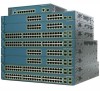
... Catalyst 3560 Switch 97916 40 41 42 43 44 45 46 47 48 47X Catalyst 3560 SERIES PoE-48 1 3 48X 2 4 Attaching Brackets to a Catalyst 3560 Switch, Front Panel Forward SYST RPS STAT DUPLX SPEED PoE MODE 1 1X 23 45 67 8 9 10 11 12 13 14 15 16 15X 2X 16X 1 Phillips flat...
... Catalyst 3560 Switch 97916 40 41 42 43 44 45 46 47 48 47X Catalyst 3560 SERIES PoE-48 1 3 48X 2 4 Attaching Brackets to a Catalyst 3560 Switch, Front Panel Forward SYST RPS STAT DUPLX SPEED PoE MODE 1 1X 23 45 67 8 9 10 11 12 13 14 15 16 15X 2X 16X 1 Phillips flat...
Hardware Installation Guide
Page 41
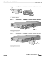
... the Switch Figure 2-3 1 Attaching Brackets for 24-Inch Racks to a Catalyst 3560 Switch, Front Panel Forward 1 Phillips flat-head screws SYST RPS STAT DUPLX SPEED PoE MODE 1 1X 23 45 67 8 9 10 11 12 13 14 15 16 15X 2X 16X 97918 Figure 2-4 Attaching Brackets for 19-Inch Racks to a Catalyst...
... the Switch Figure 2-3 1 Attaching Brackets for 24-Inch Racks to a Catalyst 3560 Switch, Front Panel Forward 1 Phillips flat-head screws SYST RPS STAT DUPLX SPEED PoE MODE 1 1X 23 45 67 8 9 10 11 12 13 14 15 16 15X 2X 16X 97918 Figure 2-4 Attaching Brackets for 19-Inch Racks to a Catalyst...
Hardware Installation Guide
Page 42
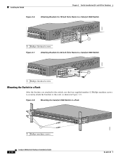
... 2-6 Attaching Brackets for 19-Inch Telco Racks to a Catalyst 3560 Switch 97921 40 41 42 43 44 45 46 47 48 47X Catalyst 3560 SERIES PoE-48 1 3 48X 2 4 1 1 Phillips flat-head screws Figure 2-7 Attaching Brackets for 24-Inch Telco Racks to a Catalyst 3560 Switch 97922 40 41 42 43 44... 45 46 47 48 47X Catalyst 3560 SERIES PoE-48 1 3 48X 2 1 4 1 Phillips flat-head screws Mounting the Switch in a Rack After the brackets are attached to the switch, use the four supplied ...
... 2-6 Attaching Brackets for 19-Inch Telco Racks to a Catalyst 3560 Switch 97921 40 41 42 43 44 45 46 47 48 47X Catalyst 3560 SERIES PoE-48 1 3 48X 2 4 1 1 Phillips flat-head screws Figure 2-7 Attaching Brackets for 24-Inch Telco Racks to a Catalyst 3560 Switch 97922 40 41 42 43 44... 45 46 47 48 47X Catalyst 3560 SERIES PoE-48 1 3 48X 2 1 4 1 Phillips flat-head screws Mounting the Switch in a Rack After the brackets are attached to the switch, use the four supplied ...
