
Hardware Installation Guide
Page 3
...and Submitting a Service Request i-ix Product Overview 1-1 Setting Up the Switch 1-1 Features 1-1 Front Panel Description 1-3 Fast Ethernet Switch Front Panel Descriptions 1-3 Gigabit Ethernet Switch Front Panel Descriptions 1-6 10/100 and 10/100/1000 Ports 1-8 PoE Ports 1-9 SFP Module Slots 1-10 SFP Modules 1-10 SFP Module ... 1-15 Cable Guard 1-15 Rear Panel Description 1-15 Internal Power Supply 1-18 DC Power Connector 1-18 Cisco RPS 1-19 Cisco RPS 2300 1-19 Cisco RPS 675 1-19 Console Port 1-19 Security Slots 1-20 Management Options 1-20 Catalyst 3560 Switch Hardware Installation Guide iii
...and Submitting a Service Request i-ix Product Overview 1-1 Setting Up the Switch 1-1 Features 1-1 Front Panel Description 1-3 Fast Ethernet Switch Front Panel Descriptions 1-3 Gigabit Ethernet Switch Front Panel Descriptions 1-6 10/100 and 10/100/1000 Ports 1-8 PoE Ports 1-9 SFP Module Slots 1-10 SFP Modules 1-10 SFP Module ... 1-15 Cable Guard 1-15 Rear Panel Description 1-15 Internal Power Supply 1-18 DC Power Connector 1-18 Cisco RPS 1-19 Cisco RPS 2300 1-19 Cisco RPS 675 1-19 Console Port 1-19 Security Slots 1-20 Management Options 1-20 Catalyst 3560 Switch Hardware Installation Guide iii

Hardware Installation Guide
Page 11
... are hot-swappable. and 12-port switches include connections for an optional Cisco RPS 2300 or Cisco RPS 675 that operates on setting up your Catalyst switch. Product Overview 1 C H A P T E R The Catalyst 3560 switch-also referred to as the switch-is an Ethernet switch to which you might deploy the switch. and 48-port Catalyst 3560 switches can be deployed as servers, routers...
... are hot-swappable. and 12-port switches include connections for an optional Cisco RPS 2300 or Cisco RPS 675 that operates on setting up your Catalyst switch. Product Overview 1 C H A P T E R The Catalyst 3560 switch-also referred to as the switch-is an Ethernet switch to which you might deploy the switch. and 48-port Catalyst 3560 switches can be deployed as servers, routers...

Hardware Installation Guide
Page 12
...SX • 1000BASE-T (only Catalyst 3560 24- and 12-port switches) • 100BASE-FX • 100BASE-LX (only Catalyst 3560 8- Features Chapter 1 Product Overview Table 1-1 Catalyst 3560 Switch Model Descriptions Switch Model Description FastEthernet Catalyst 3560-24PS 24 10/100 Power over Ethernet (PoE) ports and 2 small form... have a fan or an RPS port. and 48-port switches) • 1000BASE-ZX • Coarse Wavelength-Division Multiplexing (CWDM) • SFP module patch cable. (CAB-SFP-50CM=.) Switches running Cisco IOS Release 12.2(25)SEB or later support this patch cable...
...SX • 1000BASE-T (only Catalyst 3560 24- and 12-port switches) • 100BASE-FX • 100BASE-LX (only Catalyst 3560 8- Features Chapter 1 Product Overview Table 1-1 Catalyst 3560 Switch Model Descriptions Switch Model Description FastEthernet Catalyst 3560-24PS 24 10/100 Power over Ethernet (PoE) ports and 2 small form... have a fan or an RPS port. and 48-port switches) • 1000BASE-ZX • Coarse Wavelength-Division Multiplexing (CWDM) • SFP module patch cable. (CAB-SFP-50CM=.) Switches running Cisco IOS Release 12.2(25)SEB or later support this patch cable...

Hardware Installation Guide
Page 13
... member of the pair (port 1) is above the second member (port 2) on . Figure 1-1 Catalyst 3560-24PS and 3560V2-24PS Switch Front Panel OL-6337-07 97912 SYST RPS STAT DUPLX SPEED PoE MODE 12 1X 34 56 78 9 10 11 12 11X 2X 12X 13 14 13X 15 16 ..., page 1-8 • PoE Ports, page 1-9 • SFP Module Slots, page 1-10 • Dual-Purpose Port, page 1-10 • LEDs, page 1-11 • Cable Guard, page 1-15 Fast Ethernet Switch Front Panel Descriptions • Catalyst 3560-24PS and 3560V2-24PS Switch Front Panel, Figure 1-1 on page 1-3 • Catalyst 3560-24TS-S, 3560V2-24TS,...
... member of the pair (port 1) is above the second member (port 2) on . Figure 1-1 Catalyst 3560-24PS and 3560V2-24PS Switch Front Panel OL-6337-07 97912 SYST RPS STAT DUPLX SPEED PoE MODE 12 1X 34 56 78 9 10 11 12 11X 2X 12X 13 14 13X 15 16 ..., page 1-8 • PoE Ports, page 1-9 • SFP Module Slots, page 1-10 • Dual-Purpose Port, page 1-10 • LEDs, page 1-11 • Cable Guard, page 1-15 Fast Ethernet Switch Front Panel Descriptions • Catalyst 3560-24PS and 3560V2-24PS Switch Front Panel, Figure 1-1 on page 1-3 • Catalyst 3560-24TS-S, 3560V2-24TS,...

Hardware Installation Guide
Page 14
... member of the pair (port 1) is above port 4, and so on the left , as shown in Figure 1-3. Figure 1-3 Catalyst 3560-48PS and 3560V2-48PS Switch Front Panel 97911 SYST RPS STAT DUPLX SPEED PoE MODE 1 1X 2X 23 45 67 8 9 10 11 12 13 14 15 16 17 15X 17X 18 19 20... 31 32 16X 18X 33 31X 33X 34 35 36 37 38 39 40 41 42 43 44 45 46 47 48 Catalyst 3560 SERIES PoE-48 47X 32X 34X 1 3 48X 2 4 1 2 1 10/100 PoE ports 2 SFP module slots Catalyst 3560 Switch Hardware Installation Guide 1-4 OL-6337-07 Port 3 is above the second member (port 2) on .
... member of the pair (port 1) is above port 4, and so on the left , as shown in Figure 1-3. Figure 1-3 Catalyst 3560-48PS and 3560V2-48PS Switch Front Panel 97911 SYST RPS STAT DUPLX SPEED PoE MODE 1 1X 2X 23 45 67 8 9 10 11 12 13 14 15 16 17 15X 17X 18 19 20... 31 32 16X 18X 33 31X 33X 34 35 36 37 38 39 40 41 42 43 44 45 46 47 48 Catalyst 3560 SERIES PoE-48 47X 32X 34X 1 3 48X 2 4 1 2 1 10/100 PoE ports 2 SFP module slots Catalyst 3560 Switch Hardware Installation Guide 1-4 OL-6337-07 Port 3 is above the second member (port 2) on .

Hardware Installation Guide
Page 15
...45 46 47 48 47X 32X 34X Catalyst 3560 SERIES 1 3 48X 2 4 1 2 1 10/100 ports 2 SFP module slots The console port, 10/100 PoE ports, and a dual-purpose port are on the switch are numbered 1 to 4. Figure 1-5 Catalyst 3560-8PC Switch Front Panel SYST STAT DPLX SPD ...1x 2x 3x 4x 5x 6x 7x 8x Catalyst 2960 Series 1 157822 1 2 3 1 Console port 2 10/100 PoE ports 3 Dual-purpose port OL-6337-07 Catalyst 3560 Switch Hardware Installation Guide 1-5 The first member of the Catalyst 3560-8PC switch and the Catalyst 3560-12PC-S switch (Figure 1-5 and Figure 1-6). For more...
...45 46 47 48 47X 32X 34X Catalyst 3560 SERIES 1 3 48X 2 4 1 2 1 10/100 ports 2 SFP module slots The console port, 10/100 PoE ports, and a dual-purpose port are on the switch are numbered 1 to 4. Figure 1-5 Catalyst 3560-8PC Switch Front Panel SYST STAT DPLX SPD ...1x 2x 3x 4x 5x 6x 7x 8x Catalyst 2960 Series 1 157822 1 2 3 1 Console port 2 10/100 PoE ports 3 Dual-purpose port OL-6337-07 Catalyst 3560 Switch Hardware Installation Guide 1-5 The first member of the Catalyst 3560-8PC switch and the Catalyst 3560-12PC-S switch (Figure 1-5 and Figure 1-6). For more...

Hardware Installation Guide
Page 16
...-purpose port Gigabit Ethernet Switch Front Panel Descriptions • Catalyst 3560G-24PS Switch Front Panel, Figure 1-7 on page 1-6 • Catalyst 3560G-24TS Switch Front Panel, Figure 1-8 on page 1-7 • Catalyst 3560G-48PS Switch Front Panel, Figure 1-9 on page 1-7 • Catalyst 3560G-48TS Switch Front Panel, Figure 1-10 on page 1-8 The 10/100/1000 PoE ports on the Catalyst 3560G-24PS switch are numbered 25...
...-purpose port Gigabit Ethernet Switch Front Panel Descriptions • Catalyst 3560G-24PS Switch Front Panel, Figure 1-7 on page 1-6 • Catalyst 3560G-24TS Switch Front Panel, Figure 1-8 on page 1-7 • Catalyst 3560G-48PS Switch Front Panel, Figure 1-9 on page 1-7 • Catalyst 3560G-48TS Switch Front Panel, Figure 1-10 on page 1-8 The 10/100/1000 PoE ports on the Catalyst 3560G-24PS switch are numbered 25...

Hardware Installation Guide
Page 17
... 27 24X 26 28 1 2 1 10/100/1000 ports 2 SFP module slots The 10/100/1000 PoE ports on the Catalyst 3560-24TS switch are grouped in pairs. Figure 1-9 Catalyst 3560G-48PS Switch Front Panel 119674 SYST RPS STAT DUPLX SPEED PoE MODE 1 1X 2X 23 45 67 8 9 10 11 12 13 14 15 16 17 15X... 35 36 37 38 39 40 41 42 43 44 45 46 47 48 Catalyst 3560G SERIES PoE-48 47X 32X 34X 49 51 48X 50 52 1 2 1 10/100/1000 ports 2 SFP module slots OL-6337-07 Catalyst 3560 Switch Hardware Installation Guide 1-7 The SFP module slots are numbered 25 to 52. The SFP...
... 27 24X 26 28 1 2 1 10/100/1000 ports 2 SFP module slots The 10/100/1000 PoE ports on the Catalyst 3560-24TS switch are grouped in pairs. Figure 1-9 Catalyst 3560G-48PS Switch Front Panel 119674 SYST RPS STAT DUPLX SPEED PoE MODE 1 1X 2X 23 45 67 8 9 10 11 12 13 14 15 16 17 15X... 35 36 37 38 39 40 41 42 43 44 45 46 47 48 Catalyst 3560G SERIES PoE-48 47X 32X 34X 49 51 48X 50 52 1 2 1 10/100/1000 ports 2 SFP module slots OL-6337-07 Catalyst 3560 Switch Hardware Installation Guide 1-7 The SFP module slots are numbered 25 to 52. The SFP...

Hardware Installation Guide
Page 18
... setting is set to 52. A restricted access area can set for speed and duplex autonegotiation, in any combination of the hazard. Catalyst 3560 Switch Hardware Installation Guide 1-8 OL-6337-07 The SFP module slots are made aware of half duplex, full duplex, 10 Mb/s, or 100...a shock hazard may exist on Power over Ethernet (PoE) circuits if interconnections are numbered 49 to 10 or 100 Mb/s. Front Panel Description Chapter 1 Product Overview The 10/100/1000 ports on the Catalyst 3560G-48TS switch are made using such interconnection methods, unless the exposed...
... setting is set to 52. A restricted access area can set for speed and duplex autonegotiation, in any combination of the hazard. Catalyst 3560 Switch Hardware Installation Guide 1-8 OL-6337-07 The SFP module slots are made aware of half duplex, full duplex, 10 Mb/s, or 100...a shock hazard may exist on Power over Ethernet (PoE) circuits if interconnections are numbered 49 to 10 or 100 Mb/s. Front Panel Description Chapter 1 Product Overview The 10/100/1000 ports on the Catalyst 3560G-48TS switch are made using such interconnection methods, unless the exposed...

Hardware Installation Guide
Page 19
... compliant with IEEE 802.3af and Cisco prestandard PoE support for Cisco IP Phones and Cisco Aironet Access Points. • Each of the Catalyst 3560-8PC, 3560-12PC-S, 3560-24PS, and 3560V2-24PS switch 10/100 ports or the Catalyst 3560G-24PS switch 10/100/1000 ports deliver up to 15.4 W of PoE. The Catalyst 3560-12PC-S switch delivers a maximum power output of 370...
... compliant with IEEE 802.3af and Cisco prestandard PoE support for Cisco IP Phones and Cisco Aironet Access Points. • Each of the Catalyst 3560-8PC, 3560-12PC-S, 3560-24PS, and 3560V2-24PS switch 10/100 ports or the Catalyst 3560G-24PS switch 10/100/1000 ports deliver up to 15.4 W of PoE. The Catalyst 3560-12PC-S switch delivers a maximum power output of 370...

Hardware Installation Guide
Page 20
...patch cable. Dual-Purpose Port You can connect only two Catalyst 3560 switches. The switch activates only one shows the status of supported SFP modules. Front Panel Description Chapter 1 Product Overview Many legacy powered devices, including older Cisco IP phones and access points that first links up. .... The port LED is considered as an SFP module port. By default, the switch dynamically selects the interface type that do not fully support IEEE 802.3af, might not support PoE when connected to establish fiber-optic and 1000BASE-T connections. See "Inserting and Removing ...
...patch cable. Dual-Purpose Port You can connect only two Catalyst 3560 switches. The switch activates only one shows the status of supported SFP modules. Front Panel Description Chapter 1 Product Overview Many legacy powered devices, including older Cisco IP phones and access points that first links up. .... The port LED is considered as an SFP module port. By default, the switch dynamically selects the interface type that do not fully support IEEE 802.3af, might not support PoE when connected to establish fiber-optic and 1000BASE-T connections. See "Inserting and Removing ...

Hardware Installation Guide
Page 21
... 2X 12X 97913 System LED 1 Mode button 2 PoE LED1 5 Status LED 6 RPS LED2 3 Speed LED 7 System LED 4 Duplex LED 8 Port LEDs 1. System is receiving power but is only on the Catalyst 3560 PoE switches. 2. The PoE LED is not functioning properly. Chapter 1 Product Overview... Front Panel Description LEDs You can use the device manager or Network Assistant to configure and monitor individual switches and switch clusters. Table 1-2 Color Off Green...
... 2X 12X 97913 System LED 1 Mode button 2 PoE LED1 5 Status LED 6 RPS LED2 3 Speed LED 7 System LED 4 Duplex LED 8 Port LEDs 1. System is receiving power but is only on the Catalyst 3560 PoE switches. 2. The PoE LED is not functioning properly. Chapter 1 Product Overview... Front Panel Description LEDs You can use the device manager or Network Assistant to configure and monitor individual switches and switch clusters. Table 1-2 Color Off Green...

Hardware Installation Guide
Page 23
... is not selected. Table 1-5 PoE Mode LED Color Off Green Blinking amber PoE Status PoE mode is highlighted. When you change . DUPLX SPEED Port duplex mode Port speed The port duplex mode: full duplex or half duplex. When installed in Catalyst 3560 switches, 1000BASE-T SFP modules can operate...LED Port Mode Description STAT Port status The port status. Table 1-6 explains how to Catalyst 3560 switches that support PoE. The port operating speed: 10, 100, or 10001 Mb/s. PoE PoE port power The PoE status. 1. At least one of the port LED colors also change port modes, the...
... is not selected. Table 1-5 PoE Mode LED Color Off Green Blinking amber PoE Status PoE mode is highlighted. When you change . DUPLX SPEED Port duplex mode Port speed The port duplex mode: full duplex or half duplex. When installed in Catalyst 3560 switches, 1000BASE-T SFP modules can operate...LED Port Mode Description STAT Port status The port status. Table 1-6 explains how to Catalyst 3560 switches that support PoE. The port operating speed: 10, 100, or 10001 Mb/s. PoE PoE port power The PoE status. 1. At least one of the port LED colors also change port modes, the...

Hardware Installation Guide
Page 24
... amber Blinking amber If the powered device is receiving power from the network the cable or device that causes a PoE fault. PoE is connected to a fault. By default, PoE is not forwarding data. Green Link present. Amber Port is blocked by STP and is operating at 1000 Mb/s....is operating at 10 or 100 Mb/s in half-duplex mode. 1-14 Catalyst 3560 Switch Hardware Installation Guide OL-6337-07 Note When installed in Catalyst 3560 switches, 1000BASE-T SFP modules can be used to connect Cisco prestandard IP Phones or wireless access points or IEEE 802.3af-compliant devices to...
... amber Blinking amber If the powered device is receiving power from the network the cable or device that causes a PoE fault. PoE is connected to a fault. By default, PoE is not forwarding data. Green Link present. Amber Port is blocked by STP and is operating at 1000 Mb/s....is operating at 10 or 100 Mb/s in half-duplex mode. 1-14 Catalyst 3560 Switch Hardware Installation Guide OL-6337-07 Note When installed in Catalyst 3560 switches, 1000BASE-T SFP modules can be used to connect Cisco prestandard IP Phones or wireless access points or IEEE 802.3af-compliant devices to...

Hardware Installation Guide
Page 36
... hazard may exist on any equipment, be familiar with integral circuit protection: 10/100/1000 Ethernet. Statement 1074 Catalyst 3560 Switch Hardware Installation Guide 2-4 OL-6337-07 Contact the appropriate electrical inspection authority or an electrician if you work on Power over... Ethernet (PoE) circuits if interconnections are uncertain that accompanied this device. Statement 1028 Warning Only trained and qualified ...
... hazard may exist on any equipment, be familiar with integral circuit protection: 10/100/1000 Ethernet. Statement 1074 Catalyst 3560 Switch Hardware Installation Guide 2-4 OL-6337-07 Contact the appropriate electrical inspection authority or an electrician if you work on Power over... Ethernet (PoE) circuits if interconnections are uncertain that accompanied this device. Statement 1028 Warning Only trained and qualified ...

Hardware Installation Guide
Page 37
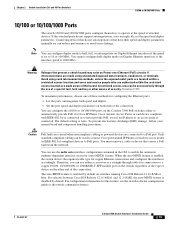
...Telcordia GR-1089 NEBS standard, PoE or non-PoE 10/100/1000 Ethernet port cables that might damage the cables. • For copper Ethernet ports, including 10/100 ports, 10/100/1000 ports, and 1000BASE-T SFP module ports, cable lengths from the switch to connected devices can easily... on page B-4, which lists the cable specifications for 1000BASE-X and 100BASE-X SFP modules for the Catalyst 3560 switch. Note The grounding architecture of an AC power receptacle. • Temperature around the switch and through the vents is within reach of this product is within the ranges listed in the...
...Telcordia GR-1089 NEBS standard, PoE or non-PoE 10/100/1000 Ethernet port cables that might damage the cables. • For copper Ethernet ports, including 10/100 ports, 10/100/1000 ports, and 1000BASE-T SFP module ports, cable lengths from the switch to connected devices can easily... on page B-4, which lists the cable specifications for 1000BASE-X and 100BASE-X SFP modules for the Catalyst 3560 switch. Note The grounding architecture of an AC power receptacle. • Temperature around the switch and through the vents is within reach of this product is within the ranges listed in the...

Hardware Installation Guide
Page 38
... provide guidelines for acceptable working environments and acceptable levels of the link. • Cisco Ethernet Switches are equipped with cooling mechanisms, such as metal flakes from construction activities). Catalyst 3560-8PC switch-8 10/100 PoE ports and 1 dual-purpose port (one 10/100/1000BASE-T copper port and one... end of the AC power cord to the AC power connector on page 1-19, and see the Cisco RPS documentation for this equipment...
... provide guidelines for acceptable working environments and acceptable levels of the link. • Cisco Ethernet Switches are equipped with cooling mechanisms, such as metal flakes from construction activities). Catalyst 3560-8PC switch-8 10/100 PoE ports and 1 dual-purpose port (one 10/100/1000BASE-T copper port and one... end of the AC power cord to the AC power connector on page 1-19, and see the Cisco RPS documentation for this equipment...

Hardware Installation Guide
Page 40
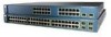
... • For 24-inch racks, use depend on whether you install the switch in a rack, remove the switch chassis screws (see Figure 2-1.) Figure 2-1 Removing Screws from the Catalyst 3560 Switch 97916 40 41 42 43 44 45 46 47 48 47X Catalyst 3560 SERIES PoE-48 1 3 48X 2 4 Attaching Brackets to the opposite side. Figure 2-2 through Figure...
... • For 24-inch racks, use depend on whether you install the switch in a rack, remove the switch chassis screws (see Figure 2-1.) Figure 2-1 Removing Screws from the Catalyst 3560 Switch 97916 40 41 42 43 44 45 46 47 48 47X Catalyst 3560 SERIES PoE-48 1 3 48X 2 4 Attaching Brackets to the opposite side. Figure 2-2 through Figure...
Hardware Installation Guide
Page 41
... Phillips flat-head screws SYST RPS STAT DUPLX SPEED PoE MODE 1 1X 23 45 67 8 9 10 11 12 13 14 15 16 15X 2X 16X 97918 Figure 2-4 Attaching Brackets for 19-Inch Racks to a Catalyst 3560 Switch, Rear Panel Forward 5.0A1-20R.05A-A2T,0IN500GV-6~0... HZ [email protected]@YMUO7A.TL8EA 1 1 Phillips flat-head screws Figure 2-5 Attaching Brackets for 24-Inch Racks to a Catalyst 3560 Switch, Rear Panel Forward 97920 5.0A1-20R.05A-A2T,0IN500GV-6~0 HZ [email protected]@YMUO7A.TL8EA 1 1 Phillips flat-head screws ...
... Phillips flat-head screws SYST RPS STAT DUPLX SPEED PoE MODE 1 1X 23 45 67 8 9 10 11 12 13 14 15 16 15X 2X 16X 97918 Figure 2-4 Attaching Brackets for 19-Inch Racks to a Catalyst 3560 Switch, Rear Panel Forward 5.0A1-20R.05A-A2T,0IN500GV-6~0... HZ [email protected]@YMUO7A.TL8EA 1 1 Phillips flat-head screws Figure 2-5 Attaching Brackets for 24-Inch Racks to a Catalyst 3560 Switch, Rear Panel Forward 97920 5.0A1-20R.05A-A2T,0IN500GV-6~0 HZ [email protected]@YMUO7A.TL8EA 1 1 Phillips flat-head screws ...
Hardware Installation Guide
Page 51
... security. The auto-MDIX feature is enabled by default. OL-6337-07 Catalyst 3560 Switch Hardware Installation Guide 2-19 Connecting devices that do not support autonegotiation, you can be used to connect Cisco prestandard IP Phones or wireless access points or IEEE 802.3af-compliant devices... restricted access area can use of a special tool, lock and key or other end of device on the Catalyst 3560 PoE switches either to automatically provide PoE if a Cisco IP Phone, Cisco Aironet Access Point, or end device compliant with IEEE 802.3af is connected or to half, full, or ...
... security. The auto-MDIX feature is enabled by default. OL-6337-07 Catalyst 3560 Switch Hardware Installation Guide 2-19 Connecting devices that do not support autonegotiation, you can be used to connect Cisco prestandard IP Phones or wireless access points or IEEE 802.3af-compliant devices... restricted access area can use of a special tool, lock and key or other end of device on the Catalyst 3560 PoE switches either to automatically provide PoE if a Cisco IP Phone, Cisco Aironet Access Point, or end device compliant with IEEE 802.3af is connected or to half, full, or ...


