
Installation Guide
Page 25
.... A feature specific to the Catalyst 3524-PWR XL switch is its ability to provide inline power to Cisco IP Phones. (Phone adapters are stackable 10/100 Ethernet switches to the Catalyst 3524-PWR XL 10/100 switch ports.) Figure 1-1 shows the switch models in different network topologies Features The Catalyst 3500 series XL switches-also referred to as Catalyst 3500 XL switches-are not required when connecting...
.... A feature specific to the Catalyst 3524-PWR XL switch is its ability to provide inline power to Cisco IP Phones. (Phone adapters are stackable 10/100 Ethernet switches to the Catalyst 3524-PWR XL 10/100 switch ports.) Figure 1-1 shows the switch models in different network topologies Features The Catalyst 3500 series XL switches-also referred to as Catalyst 3500 XL switches-are not required when connecting...

Installation Guide
Page 26
... 1 Product Overview Figure 1-1 Catalyst 3500 Series XL Switches Switch Description WS-C3508G-XL 8 GBIC1-based gigabit module slots 1 SYSTEM 2 3 RPS 4 5 MODE STATUS UTIL DUPLX SPEED 6 7 8 WS-C3512-XL 12 autosensing10/100 Ethernet ports 2 GBIC-based gigabit module slots WS-C3524-XL 24 autosensing 10/100 Ethernet ports 2 fixed GBIC-based gigabit module slots WS-C3524-PWR-XL 24 autosensing 10/100 inline-power Ethernet ports...
... 1 Product Overview Figure 1-1 Catalyst 3500 Series XL Switches Switch Description WS-C3508G-XL 8 GBIC1-based gigabit module slots 1 SYSTEM 2 3 RPS 4 5 MODE STATUS UTIL DUPLX SPEED 6 7 8 WS-C3512-XL 12 autosensing10/100 Ethernet ports 2 GBIC-based gigabit module slots WS-C3524-XL 24 autosensing 10/100 Ethernet ports 2 fixed GBIC-based gigabit module slots WS-C3524-PWR-XL 24 autosensing 10/100 inline-power Ethernet ports...

Installation Guide
Page 28
Features Chapter 1 Product Overview Table 1-2 Catalyst 3512, 3524, 3524-PWR, and 3548 XL Features Feature Performance and Configuration Description • Autonegotiation of speed and duplex operation on 10/100 Ethernet ports • 12, 24, or 48 10/100 Ethernet ports and 2 GBIC-based Gigabit Ethernet slots...; SPAN port monitoring on any port • Support for command switch redundancy • Support for Cisco GBIC modules - GigaStack GBIC - 1000BaseSX GBIC module - 1000BaseLX/LH GBIC module - 1000BaseZX GBIC module Catalyst 3500 Series XL Hardware Installation Guide 1-4 78-6456-04
Features Chapter 1 Product Overview Table 1-2 Catalyst 3512, 3524, 3524-PWR, and 3548 XL Features Feature Performance and Configuration Description • Autonegotiation of speed and duplex operation on 10/100 Ethernet ports • 12, 24, or 48 10/100 Ethernet ports and 2 GBIC-based Gigabit Ethernet slots...; SPAN port monitoring on any port • Support for command switch redundancy • Support for Cisco GBIC modules - GigaStack GBIC - 1000BaseSX GBIC module - 1000BaseLX/LH GBIC module - 1000BaseZX GBIC module Catalyst 3500 Series XL Hardware Installation Guide 1-4 78-6456-04

Installation Guide
Page 29
... supplies DC output to the Catalyst 3512, 3524, and 3548 XL switches • Connection for optional Cisco RPS 300 that operates on AC input and supplies DC output to the Catalyst 3524-PWR XL switch Inline Power (Catalyst 3524-PWR XL switch only) • Ability to provide inline power for Cisco IP Phones from all 24 10/100 Ethernet ports • Auto-detection...
... supplies DC output to the Catalyst 3512, 3524, and 3548 XL switches • Connection for optional Cisco RPS 300 that operates on AC input and supplies DC output to the Catalyst 3524-PWR XL switch Inline Power (Catalyst 3524-PWR XL switch only) • Ability to provide inline power for Cisco IP Phones from all 24 10/100 Ethernet ports • Auto-detection...

Installation Guide
Page 31
...Cisco IP Phones, and hubs through standard RJ-45 connectors and Category 3, 4, or 5 cabling 78-6456-04 Catalyst 3500 Series XL Hardware Installation Guide 1-7 Port 3 is above port 4, and so on the Catalyst 3512, 3524, 3524-PWR, and 3548 XL switches are the left-most pair. Chapter 1 Product Overview Figure 1-5 Catalyst 3524-PWR XL Switch...56 78 MODE SYSTEM RPS STATUS 2X DUPLX SPEED LINE PWR 9 10 11 12 11X 12X 13 14 13X 15 16 17 18 19 20 21 22 23 24 23X 14X 24X 10/100 inline-power ports Figure 1-6 Catalyst 3548 XL Switch 1 2 GBIC module slots 28010 SYSTEM RPS 12 1X...
...Cisco IP Phones, and hubs through standard RJ-45 connectors and Category 3, 4, or 5 cabling 78-6456-04 Catalyst 3500 Series XL Hardware Installation Guide 1-7 Port 3 is above port 4, and so on the Catalyst 3512, 3524, 3524-PWR, and 3548 XL switches are the left-most pair. Chapter 1 Product Overview Figure 1-5 Catalyst 3524-PWR XL Switch...56 78 MODE SYSTEM RPS STATUS 2X DUPLX SPEED LINE PWR 9 10 11 12 11X 12X 13 14 13X 15 16 17 18 19 20 21 22 23 24 23X 14X 24X 10/100 inline-power ports Figure 1-6 Catalyst 3548 XL Switch 1 2 GBIC module slots 28010 SYSTEM RPS 12 1X...

Installation Guide
Page 32
When connecting the switch to workstations, servers, routers, and Cisco IP Phones, be explicitly set to the 10/100 ports on the Catalyst 3512, 3524, 3524-PWR, and 3548 XL switches provide protocol support for Cisco IP Phones. The 10/100 switch ports can be sure that both devices support and full-duplex transmission, if the attached device supports it) and configures...
When connecting the switch to workstations, servers, routers, and Cisco IP Phones, be explicitly set to the 10/100 ports on the Catalyst 3512, 3524, 3524-PWR, and 3548 XL switches provide protocol support for Cisco IP Phones. The 10/100 switch ports can be sure that both devices support and full-duplex transmission, if the attached device supports it) and configures...

Installation Guide
Page 33
... is connected to it . The GigaStack GBIC supports one full-duplex link (in the Catalyst 3508G XL switch. You can connect the Cisco IP Phone to a Catalyst 3524-PWR XL 10/100 port and to nine Catalyst 3500 XL switches. Figure 1-7 and Figure 1-8 show how a GBIC module is its primary power source,... and the second power source is inserted into a GBIC module slot on these switches, but you select the...
... is connected to it . The GigaStack GBIC supports one full-duplex link (in the Catalyst 3508G XL switch. You can connect the Cisco IP Phone to a Catalyst 3524-PWR XL 10/100 port and to nine Catalyst 3500 XL switches. Figure 1-7 and Figure 1-8 show how a GBIC module is its primary power source,... and the second power source is inserted into a GBIC module slot on these switches, but you select the...

Installation Guide
Page 39
... RPS. For more information see the "RPS Connector on the Catalyst 3508, 3512, 3524, and 3548 XL Switches" section on . Note The Cisco RPS 300 (model PWR300-AC-RPS) supports the Catalyst 3524-PWR XL switch. 78-6456-04 Catalyst 3500 Series XL Hardware Installation Guide 1-15 Note The Cisco RPS 600 (model PWR600-AC-RPS) supports the...
... RPS. For more information see the "RPS Connector on the Catalyst 3508, 3512, 3524, and 3548 XL Switches" section on . Note The Cisco RPS 300 (model PWR300-AC-RPS) supports the Catalyst 3524-PWR XL switch. 78-6456-04 Catalyst 3500 Series XL Hardware Installation Guide 1-15 Note The Cisco RPS 600 (model PWR600-AC-RPS) supports the...

Installation Guide
Page 40
...highlighted. This is not installed. Port LEDs and Modes Each 10/100 port and module slot has a port LED. The current bandwidth in the stack. Internal power supply of the power supplies in the Catalyst 3548 XL switch, press the Mode label. When you change port modes, ... Table 1-8 explain how to the Cisco Redundant Power System 300 Hardware Installation Guide. To select or change the port mode in the RPS could have failed. Front-Panel Description Chapter 1 Product Overview Table 1-5 RPS LED for the Catalyst 3524-PWR XL Switch Color Off Solid green Blinking green ...
...highlighted. This is not installed. Port LEDs and Modes Each 10/100 port and module slot has a port LED. The current bandwidth in the stack. Internal power supply of the power supplies in the Catalyst 3548 XL switch, press the Mode label. When you change port modes, ... Table 1-8 explain how to the Cisco Redundant Power System 300 Hardware Installation Guide. To select or change the port mode in the RPS could have failed. Front-Panel Description Chapter 1 Product Overview Table 1-5 RPS LED for the Catalyst 3524-PWR XL Switch Color Off Solid green Blinking green ...

Installation Guide
Page 41
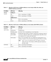
... Hardware Installation Guide 1-17 Chapter 1 Product Overview Front-Panel Description Table 1-6 Port Mode LEDs (continued) Mode LED DUPLX SPEED LINE PWR Port Mode Port duplex mode Port speed Port inline power Description The port duplex mode: full duplex or half duplex. Link fault. ..., and so on the Catalyst 3508, 3512, 3524, and 3548 XL Switches Port Mode STATUS (port status) UTL (utilization) DUPLEX LED Color Off Solid green Flashing green Alternating green-amber Solid amber Green Off Green Meaning No link. Activity. The port operating speed: 10, 100, or 1000 Mbps. Port...
... Hardware Installation Guide 1-17 Chapter 1 Product Overview Front-Panel Description Table 1-6 Port Mode LEDs (continued) Mode LED DUPLX SPEED LINE PWR Port Mode Port duplex mode Port speed Port inline power Description The port duplex mode: full duplex or half duplex. Link fault. ..., and so on the Catalyst 3508, 3512, 3524, and 3548 XL Switches Port Mode STATUS (port status) UTL (utilization) DUPLEX LED Color Off Solid green Flashing green Alternating green-amber Solid amber Green Off Green Meaning No link. Activity. The port operating speed: 10, 100, or 1000 Mbps. Port...
Installation Guide
Page 42
...in Different Modes on the Catalyst 3524-PWR XL Switch Port Mode STATUS (port status) DUPLEX LED Color Off Solid green Flashing green Alternating green-amber Solid amber Off Green Meaning No link. Note After a port is operating in full duplex. 1-18 Catalyst 3500 Series XL Hardware ...Tree Protocol (STP). Front-Panel Description Chapter 1 Product Overview Table 1-7 Meaning of LED Colors in Different Modes on the Catalyst 3508, 3512, 3524, and 3548 XL Switches (continued) Port Mode SPEED (speed) LED Color 10/100 ports Off Green 1000BaseX ports Off Green Meaning Port is operating at...
...in Different Modes on the Catalyst 3524-PWR XL Switch Port Mode STATUS (port status) DUPLEX LED Color Off Solid green Flashing green Alternating green-amber Solid amber Off Green Meaning No link. Note After a port is operating in full duplex. 1-18 Catalyst 3500 Series XL Hardware ...Tree Protocol (STP). Front-Panel Description Chapter 1 Product Overview Table 1-7 Meaning of LED Colors in Different Modes on the Catalyst 3508, 3512, 3524, and 3548 XL Switches (continued) Port Mode SPEED (speed) LED Color 10/100 ports Off Green 1000BaseX ports Off Green Meaning Port is operating at...
Installation Guide
Page 43
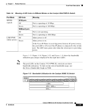
...16 show bandwidth utilization. To find out the switch bandwidth usage, use the Device Bandwidth Graph on the Catalyst 3524-PWR XL switch do not show the bandwidth utilization percentages displayed by the right-most LEDs. Port is off . If the Cisco IP Phone is receiving power from an AC ... 1 Product Overview Front-Panel Description Table 1-8 Meaning of LED Colors in Different Modes on . Inline power is on the Catalyst 3524-PWR XL Switch Port Mode LED Color SPEED (speed) 10/100 ports Off Green 1000BaseX ports Off Green LINE PWR Off (inline power) Green Meaning Port is operating at...
...16 show bandwidth utilization. To find out the switch bandwidth usage, use the Device Bandwidth Graph on the Catalyst 3524-PWR XL switch do not show the bandwidth utilization percentages displayed by the right-most LEDs. Port is off . If the Cisco IP Phone is receiving power from an AC ... 1 Product Overview Front-Panel Description Table 1-8 Meaning of LED Colors in Different Modes on . Inline power is on the Catalyst 3524-PWR XL Switch Port Mode LED Color SPEED (speed) 10/100 ports Off Green 1000BaseX ports Off Green LINE PWR Off (inline power) Green Meaning Port is operating at...

Installation Guide
Page 46
...Panel Description Figure 1-19 Catalyst 3524-PWR XL Rear Panel RATING 100-127/200-240V~ 3.5A/1.8A 50-60HZ DC INPUTS FOR REMOTE POWER SUPPLY SPECIFIED IN MANUAL. -48V @3A, +12V @6A CONSOLE AC power connector Redundant power system connector RJ-45 console port Figure 1-20 Catalyst 3548 XL Rear Panel [email protected] CONSOLE AC power connector Fan exhaust RJ-45 console port Redundant power system connector Power Connectors You can provide power to the switch either through the internal power supply or through the Cisco RPS. 1-22 Catalyst 3500 Series XL Hardware Installation Guide 78-6456-04
...Panel Description Figure 1-19 Catalyst 3524-PWR XL Rear Panel RATING 100-127/200-240V~ 3.5A/1.8A 50-60HZ DC INPUTS FOR REMOTE POWER SUPPLY SPECIFIED IN MANUAL. -48V @3A, +12V @6A CONSOLE AC power connector Redundant power system connector RJ-45 console port Figure 1-20 Catalyst 3548 XL Rear Panel [email protected] CONSOLE AC power connector Fan exhaust RJ-45 console port Redundant power system connector Power Connectors You can provide power to the switch either through the internal power supply or through the Cisco RPS. 1-22 Catalyst 3500 Series XL Hardware Installation Guide 78-6456-04

Installation Guide
Page 47
...DC output power module for four external devices that supports input voltages between 100 and 240 VAC. The power source is quasi-redundant because there are two AC input power modules for the Cisco RPS and one connector at each cable end) to connect four external... in the RPS documentation. Cisco RPS Connector Specific Cisco RPS models support specific Catalyst 3500 XL switches: • Cisco RPS 600 (model PWR600-AC-RPS)-Supports the Catalyst 3512, 3524, 3548, and 3508 XL switches • Cisco RPS 300 (model PWR300-AC-RPS)-Supports the Catalyst 3524-PWR XL switch RPS Connector on RPS. ...
...DC output power module for four external devices that supports input voltages between 100 and 240 VAC. The power source is quasi-redundant because there are two AC input power modules for the Cisco RPS and one connector at each cable end) to connect four external... in the RPS documentation. Cisco RPS Connector Specific Cisco RPS models support specific Catalyst 3500 XL switches: • Cisco RPS 600 (model PWR600-AC-RPS)-Supports the Catalyst 3512, 3524, 3548, and 3508 XL switches • Cisco RPS 300 (model PWR300-AC-RPS)-Supports the Catalyst 3524-PWR XL switch RPS Connector on RPS. ...

Installation Guide
Page 48
...powered. It provides a fully-redundant power source for these applications. 1-24 Catalyst 3500 Series XL Hardware Installation Guide 78-6456-04 You can order a kit (part number ACS-DSBUASYN=) containing that you want to connect the switch console port to a terminal. You use the Cluster Builder, Cluster ... by means of 300W. Although it supports up to the RPS receptacle. Management Options Chapter 1 Product Overview RPS Connector on the Catalyst 3524-PWR XL Switch The Cisco RPS 300 (model PWR300-AC-RPS) has two output levels: -48V and 12V with a total output power of the console ...
...powered. It provides a fully-redundant power source for these applications. 1-24 Catalyst 3500 Series XL Hardware Installation Guide 78-6456-04 You can order a kit (part number ACS-DSBUASYN=) containing that you want to connect the switch console port to a terminal. You use the Cluster Builder, Cluster ... by means of 300W. Although it supports up to the RPS receptacle. Management Options Chapter 1 Product Overview RPS Connector on the Catalyst 3524-PWR XL Switch The Cisco RPS 300 (model PWR300-AC-RPS) has two output levels: -48V and 12V with a total output power of the console ...

Installation Guide
Page 55
... includes voice and data subnetworks, where Cisco IP Phones are created by clustering the Catalyst switches except the Catalyst 4908G-L3 switch. Users with RJ-45 connectors-to the 10/100 inline-power ports on the Catalyst 3524-PWR XL switches and to the 10/100 ports on the Catalyst 3500 and 2900 XL switches. You can group the switches into multiple clusters, as a call...
... includes voice and data subnetworks, where Cisco IP Phones are created by clustering the Catalyst switches except the Catalyst 4908G-L3 switch. Users with RJ-45 connectors-to the 10/100 inline-power ports on the Catalyst 3524-PWR XL switches and to the 10/100 ports on the Catalyst 3500 and 2900 XL switches. You can group the switches into multiple clusters, as a call...
Installation Guide
Page 56
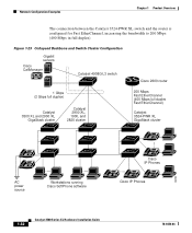
... duplex). Figure 1-23 Collapsed Backbone and Switch Cluster Configuration Gigabit servers Cisco CallManager Catalyst 4908G-L3 switch Cisco 2600 router 1 Gbps (2 Gbps full duplex) Catalyst 3500 XL and 2900 XL GigaStack cluster Catalyst 2900 XL, 1900, and 2820 cluster 200 Mbps Fast EtherChannel (400 Mbps full duplex Fast EtherChannel) Catalyst 3524-PWR XL GigaStack cluster IP IP AC power...
... duplex). Figure 1-23 Collapsed Backbone and Switch Cluster Configuration Gigabit servers Cisco CallManager Catalyst 4908G-L3 switch Cisco 2600 router 1 Gbps (2 Gbps full duplex) Catalyst 3500 XL and 2900 XL GigaStack cluster Catalyst 2900 XL, 1900, and 2820 cluster 200 Mbps Fast EtherChannel (400 Mbps full duplex Fast EtherChannel) Catalyst 3524-PWR XL GigaStack cluster IP IP AC power...
Installation Guide
Page 58
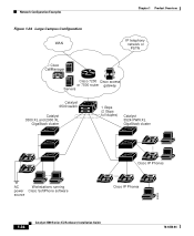
Network Configuration Examples Chapter 1 Product Overview Figure 1-24 Large Campus Configuration WAN IP telephony network or PSTN Cisco CallManager Cisco 7200 Cisco access or 7500 router gateway Servers Catalyst 6500 switch Catalyst 3500 XL and 2900 XL GigaStack cluster 1 Gbps (2 Gbps full duplex) Catalyst 3524-PWR XL GigaStack cluster IP IP AC Workstations running power Cisco SoftPhone software source IP IP Cisco IP Phones IP IP IP Cisco IP Phones 33093 1-34 Catalyst 3500 Series XL Hardware Installation Guide 78-6456-04
Network Configuration Examples Chapter 1 Product Overview Figure 1-24 Large Campus Configuration WAN IP telephony network or PSTN Cisco CallManager Cisco 7200 Cisco access or 7500 router gateway Servers Catalyst 6500 switch Catalyst 3500 XL and 2900 XL GigaStack cluster 1 Gbps (2 Gbps full duplex) Catalyst 3524-PWR XL GigaStack cluster IP IP AC Workstations running power Cisco SoftPhone software source IP IP Cisco IP Phones IP IP IP Cisco IP Phones 33093 1-34 Catalyst 3500 Series XL Hardware Installation Guide 78-6456-04
Installation Guide
Page 63
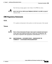
... radio frequency interference, under such circumstances, the user may be requested to the RPS receptacle. regulatory information for Installation The following warning applies to the Catalyst 3524-PWR XL switch: Warning Attach only the Cisco RPS (model PWR300-AC-RPS-N1) to take appropriate countermeasures. Statement 257 78-6456-04...
... radio frequency interference, under such circumstances, the user may be requested to the RPS receptacle. regulatory information for Installation The following warning applies to the Catalyst 3524-PWR XL switch: Warning Attach only the Cisco RPS (model PWR300-AC-RPS-N1) to take appropriate countermeasures. Statement 257 78-6456-04...
Installation Guide
Page 68
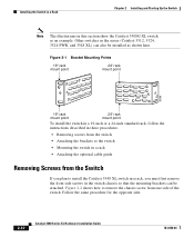
...for the opposite side. 2-10 Catalyst 3500 Series XL Hardware Installation Guide 78-6456-04 Figure 2-1 Bracket Mounting Points 19" rack mount point 24" rack mount point 38398 19" rack mount point 24" rack mount point To install the switch in a 19-inch or a 24-inch standard rack, follow... Removing screws from the switch • Attaching the brackets to the switch • Mounting the switch in a rack • Attaching the optional cable guide Removing Screws from the Switch If you must first remove the front side screws in the series (Catalyst 3512, 3524, 3524-PWR, and 3548 XL) ...
...for the opposite side. 2-10 Catalyst 3500 Series XL Hardware Installation Guide 78-6456-04 Figure 2-1 Bracket Mounting Points 19" rack mount point 24" rack mount point 38398 19" rack mount point 24" rack mount point To install the switch in a 19-inch or a 24-inch standard rack, follow... Removing screws from the switch • Attaching the brackets to the switch • Mounting the switch in a rack • Attaching the optional cable guide Removing Screws from the Switch If you must first remove the front side screws in the series (Catalyst 3512, 3524, 3524-PWR, and 3548 XL) ...