Installation Guide
Page 18
...: http://www.cisco.com International Cisco websites can access the most current Cisco documentation on each window. • Release Notes for the Catalyst 2900 Series XL and Catalyst 3500 Series XL Cisco IOS Release 12.0(5)XU • Catalyst GigaStack Gigabit Interface Converter Hardware Installation Guide • Release Notes for using a Web browser to change configuration settings and to display switch information.
...: http://www.cisco.com International Cisco websites can access the most current Cisco documentation on each window. • Release Notes for the Catalyst 2900 Series XL and Catalyst 3500 Series XL Cisco IOS Release 12.0(5)XU • Catalyst GigaStack Gigabit Interface Converter Hardware Installation Guide • Release Notes for using a Web browser to change configuration settings and to display switch information.

Installation Guide
Page 26
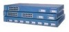
Features Chapter 1 Product Overview Figure 1-1 Catalyst 3500 Series XL Switches Switch Description WS-C3508G-XL 8 GBIC1-based gigabit module slots 1 SYSTEM 2 3 RPS 4 5 MODE STATUS UTIL DUPLX SPEED 6 7 8 WS-C3512-XL 12 autosensing10/100 Ethernet ports 2 GBIC-based gigabit module slots WS-C3524-XL 24 autosensing 10/100 Ethernet ports 2 fixed GBIC-based gigabit module slots WS-C3524-PWR-XL 24 autosensing 10/100 inline-power...
Features Chapter 1 Product Overview Figure 1-1 Catalyst 3500 Series XL Switches Switch Description WS-C3508G-XL 8 GBIC1-based gigabit module slots 1 SYSTEM 2 3 RPS 4 5 MODE STATUS UTIL DUPLX SPEED 6 7 8 WS-C3512-XL 12 autosensing10/100 Ethernet ports 2 GBIC-based gigabit module slots WS-C3524-XL 24 autosensing 10/100 Ethernet ports 2 fixed GBIC-based gigabit module slots WS-C3524-PWR-XL 24 autosensing 10/100 inline-power...

Installation Guide
Page 28
Features Chapter 1 Product Overview Table 1-2 Catalyst 3512, 3524, 3524-PWR, and 3548 XL Features Feature Performance and Configuration Description • Autonegotiation of speed and duplex operation on 10/100 Ethernet ports • 12, 24, or 48 10/100 Ethernet ports and 2 GBIC-... broadcast storms • SPAN port monitoring on any port • Support for command switch redundancy • Support for Cisco GBIC modules - GigaStack GBIC - 1000BaseSX GBIC module - 1000BaseLX/LH GBIC module - 1000BaseZX GBIC module Catalyst 3500 Series XL Hardware Installation Guide 1-4 78-6456-04
Features Chapter 1 Product Overview Table 1-2 Catalyst 3512, 3524, 3524-PWR, and 3548 XL Features Feature Performance and Configuration Description • Autonegotiation of speed and duplex operation on 10/100 Ethernet ports • 12, 24, or 48 10/100 Ethernet ports and 2 GBIC-... broadcast storms • SPAN port monitoring on any port • Support for command switch redundancy • Support for Cisco GBIC modules - GigaStack GBIC - 1000BaseSX GBIC module - 1000BaseLX/LH GBIC module - 1000BaseZX GBIC module Catalyst 3500 Series XL Hardware Installation Guide 1-4 78-6456-04
Installation Guide
Page 30
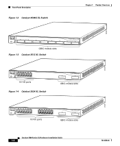
...STATUS UTIL DUPLX SPEED 2 3 4 5 6 7 8 GBIC module slots Figure 1-3 Catalyst 3512 XL Switch 12 1X 34 56 78 SYSTEM MODE RPS 2X STATUS UTIL DUPLX SPEED 9 10 11 12 11X 12X 10/100 ports Figure 1-4 Catalyst 3524 XL Switch 1 2 GBIC module slots 12 1X 34 56 78 MODE SYSTEM RPS STATUS 2X UTIL DUPLX SPEED 9 10... 11 12 11X 12X 13 14 13X 15 16 17 18 19 20...
...STATUS UTIL DUPLX SPEED 2 3 4 5 6 7 8 GBIC module slots Figure 1-3 Catalyst 3512 XL Switch 12 1X 34 56 78 SYSTEM MODE RPS 2X STATUS UTIL DUPLX SPEED 9 10 11 12 11X 12X 10/100 ports Figure 1-4 Catalyst 3524 XL Switch 1 2 GBIC module slots 12 1X 34 56 78 MODE SYSTEM RPS STATUS 2X UTIL DUPLX SPEED 9 10... 11 12 11X 12X 13 14 13X 15 16 17 18 19 20...

Installation Guide
Page 31
... 16 17 18 19 20 21 22 23 24 23X 14X 24X 10/100 inline-power ports Figure 1-6 Catalyst 3548 XL Switch 1 2 GBIC module slots 28010 SYSTEM RPS 12 1X 34 56 78 9 10 11 12 13 14 15 16 15X 17 18 17X 19 20 21 22 23 24 25 26 27 28 29... ports on . Port 3 is above port 4, and so on the Catalyst 3512, 3524, 3524-PWR, and 3548 XL switches are the left-most pair. The 10/100 switch ports can connect, up to any compatible network device: • 10BaseT-compatible devices such as workstations, Cisco IP Phones, and hubs through standard RJ-45 connectors and...
... 16 17 18 19 20 21 22 23 24 23X 14X 24X 10/100 inline-power ports Figure 1-6 Catalyst 3548 XL Switch 1 2 GBIC module slots 28010 SYSTEM RPS 12 1X 34 56 78 9 10 11 12 13 14 15 16 15X 17 18 17X 19 20 21 22 23 24 25 26 27 28 29... ports on . Port 3 is above port 4, and so on the Catalyst 3512, 3524, 3524-PWR, and 3548 XL switches are the left-most pair. The 10/100 switch ports can connect, up to any compatible network device: • 10BaseT-compatible devices such as workstations, Cisco IP Phones, and hubs through standard RJ-45 connectors and...
Installation Guide
Page 35
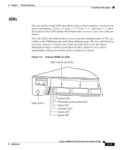
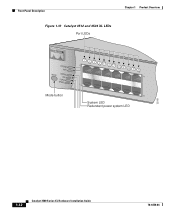
... Redundant power system LED Status LED Utilization LED Duplex LED Speed LED 78-6456-04 Catalyst 3500 Series XL Hardware Installation Guide 1-11 Figure 1-9, Figure 1-10, Figure 1-11, and Figure 1-12 show the location of the LEDs and the Mode button that you use cluster management ... Product Overview Front-Panel Description LEDs You can use the switch LEDs described in this section except the utilization meter (UTL) are visible on the VSM home page and Cluster Manager page. The Cisco IOS Desktop Switching Software Configuration Guide describes how to use the Cluster Management Suite...
... Redundant power system LED Status LED Utilization LED Duplex LED Speed LED 78-6456-04 Catalyst 3500 Series XL Hardware Installation Guide 1-11 Figure 1-9, Figure 1-10, Figure 1-11, and Figure 1-12 show the location of the LEDs and the Mode button that you use cluster management ... Product Overview Front-Panel Description LEDs You can use the switch LEDs described in this section except the utilization meter (UTL) are visible on the VSM home page and Cluster Manager page. The Cisco IOS Desktop Switching Software Configuration Guide describes how to use the Cluster Management Suite...
Installation Guide
Page 36
Front-Panel Description Figure 1-10 Catalyst 3512 and 3524 XL LEDs Port LEDs Chapter 1 Product Overview SYSTEM RPS MODE STATUS UTIL DUPLX SPEED Mode button 1 1X 23 45 67 8 9 10 11 12 11X 2X 12X System LED Redundant power system LED 22028 1-12 Catalyst 3500 Series XL Hardware Installation Guide 78-6456-04
Front-Panel Description Figure 1-10 Catalyst 3512 and 3524 XL LEDs Port LEDs Chapter 1 Product Overview SYSTEM RPS MODE STATUS UTIL DUPLX SPEED Mode button 1 1X 23 45 67 8 9 10 11 12 11X 2X 12X System LED Redundant power system LED 22028 1-12 Catalyst 3500 Series XL Hardware Installation Guide 78-6456-04

Installation Guide
Page 38
For information on the System LED colors during POST, see the "Powering On the Switch and Running POST" section on . System is receiving power but is functioning properly. Front-Panel Description Figure 1-12 Catalyst 3548 XL LEDs Port LEDs Chapter 1 Product Overview SYSTEM RPS STATUS UTIL DUPLX SPEED MODE 1 ...1X 23 45 67 8 9 10 11 12 13 14 15 16 15X 2X System LED 28325 16X Mode label ...
For information on the System LED colors during POST, see the "Powering On the Switch and Running POST" section on . System is receiving power but is functioning properly. Front-Panel Description Figure 1-12 Catalyst 3548 XL LEDs Port LEDs Chapter 1 Product Overview SYSTEM RPS STATUS UTIL DUPLX SPEED MODE 1 ...1X 23 45 67 8 9 10 11 12 13 14 15 16 15X 2X System LED 28325 16X Mode label ...
Installation Guide
Page 44
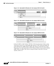
...Bandwidth Utilization for the Catalyst 3512 XL Switch MODE SYSTEM RPS STATUS UTIL DUPLX SPEED 12 1X 34 56 78 9 10 11 12 11X 2X 12X < 25% + 25% - 49% + 50% + Catalyst 3500 XL 1 2 22007 Figure 1-15 Bandwidth Utilization for the Catalyst 3524 XL Switch MODE SYSTEM RPS STATUS UTIL DUPLX SPEED 12 1X 34 56 78 ...24 15X 14X 16X < 25% + 25% - 49% + 50% + Catalyst 3500 XL 1 2 Figure 1-16 Bandwidth Utilization for the Catalyst 3548 XL Switch 28366 SYSTEM RPS STATUS UTIL DUPLX SPEED MODE 12 1X 3 24 56 78 9 10 11 12 13 14 15 16 15X 17 18 17X 19 20 21 22 23 24...
...Bandwidth Utilization for the Catalyst 3512 XL Switch MODE SYSTEM RPS STATUS UTIL DUPLX SPEED 12 1X 34 56 78 9 10 11 12 11X 2X 12X < 25% + 25% - 49% + 50% + Catalyst 3500 XL 1 2 22007 Figure 1-15 Bandwidth Utilization for the Catalyst 3524 XL Switch MODE SYSTEM RPS STATUS UTIL DUPLX SPEED 12 1X 34 56 78 ...24 15X 14X 16X < 25% + 25% - 49% + 50% + Catalyst 3500 XL 1 2 Figure 1-16 Bandwidth Utilization for the Catalyst 3548 XL Switch 28366 SYSTEM RPS STATUS UTIL DUPLX SPEED MODE 12 1X 3 24 56 78 9 10 11 12 13 14 15 16 15X 17 18 17X 19 20 21 22 23 24...

Installation Guide
Page 46
...SPECIFIED IN MANUAL. -48V @3A, +12V @6A CONSOLE AC power connector Redundant power system connector RJ-45 console port Figure 1-20 Catalyst 3548 XL Rear Panel Chapter 1 Product Overview Fans 30293 28012 RATING 100-127/200-240V~ 1.6A/0.9A 50-60HZ DC INPUTS FOR REMOTE POWER ... MANUAL +3.3V @17A, +12 @1.1A CONSOLE AC power connector Fan exhaust RJ-45 console port Redundant power system connector Power Connectors You can provide power to the switch either through the internal power supply or through the Cisco RPS. 1-22 Catalyst 3500 Series XL Hardware Installation Guide 78-6456-...
...SPECIFIED IN MANUAL. -48V @3A, +12V @6A CONSOLE AC power connector Redundant power system connector RJ-45 console port Figure 1-20 Catalyst 3548 XL Rear Panel Chapter 1 Product Overview Fans 30293 28012 RATING 100-127/200-240V~ 1.6A/0.9A 50-60HZ DC INPUTS FOR REMOTE POWER ... MANUAL +3.3V @17A, +12 @1.1A CONSOLE AC power connector Fan exhaust RJ-45 console port Redundant power system connector Power Connectors You can provide power to the switch either through the internal power supply or through the Cisco RPS. 1-22 Catalyst 3500 Series XL Hardware Installation Guide 78-6456-...
Installation Guide
Page 66
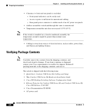
... items: • Quick Start: Catalyst 3500 Series XL Cabling and Setup • This Catalyst 3500 Series XL Hardware Installation Guide • Cisco IOS Desktop Switching Software Configuration Guide • Release Notes for the Catalyst 2900 Series XL and Catalyst 3500 Series XL Cisco IOS Release 12.0(5)XU • Cisco Documentation CD-ROM • AC power cord Catalyst 3500 Series XL Hardware Installation Guide 2-8 78-6456...
... items: • Quick Start: Catalyst 3500 Series XL Cabling and Setup • This Catalyst 3500 Series XL Hardware Installation Guide • Cisco IOS Desktop Switching Software Configuration Guide • Release Notes for the Catalyst 2900 Series XL and Catalyst 3500 Series XL Cisco IOS Release 12.0(5)XU • Cisco Documentation CD-ROM • AC power cord Catalyst 3500 Series XL Hardware Installation Guide 2-8 78-6456...

Installation Guide
Page 70
..., PLY DC INPUT +12V***@3A 24" Configuration Phillips flat-head screws Phillips truss-head screws 22440 2-12 Catalyst 3500 Series XL Hardware Installation Guide 78-6456-04 Installing the Switch in a Rack Chapter 2 Installing and Starting Up the Switch Phillips truss-head screws 1 SYSTEM RPS MODE STATUS UTIL DUPLX SPEED 2 3 24" Configuration Figure 2-4 Attaching Brackets...
..., PLY DC INPUT +12V***@3A 24" Configuration Phillips flat-head screws Phillips truss-head screws 22440 2-12 Catalyst 3500 Series XL Hardware Installation Guide 78-6456-04 Installing the Switch in a Rack Chapter 2 Installing and Starting Up the Switch Phillips truss-head screws 1 SYSTEM RPS MODE STATUS UTIL DUPLX SPEED 2 3 24" Configuration Figure 2-4 Attaching Brackets...
Installation Guide
Page 71
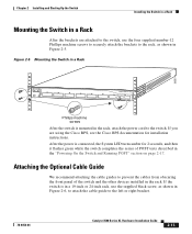
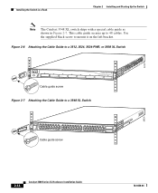
...Switch Installing the Switch in a Rack Mounting the Switch in a Rack After the brackets are using the Cisco RPS, see the Cisco RPS documentation for 2 seconds, and then it flashes green while the switch completes the series of the switch...Switch in a Rack 26233 1 SYSTEM 2 3 RPS 4 5 MODE STATUS 6 7 UTIL 8 DUPLX SPEED Phillips machine screws After the switch is in a 19-inch or 24-inch rack, use the four supplied number-12...described in Figure 2-6, to attach the cable guide to the switch. If you are attached to the switch, use the supplied black screw, as shown in the ...
...Switch Installing the Switch in a Rack Mounting the Switch in a Rack After the brackets are using the Cisco RPS, see the Cisco RPS documentation for 2 seconds, and then it flashes green while the switch completes the series of the switch...Switch in a Rack 26233 1 SYSTEM 2 3 RPS 4 5 MODE STATUS 6 7 UTIL 8 DUPLX SPEED Phillips machine screws After the switch is in a 19-inch or 24-inch rack, use the four supplied number-12...described in Figure 2-6, to attach the cable guide to the switch. If you are attached to the switch, use the supplied black screw, as shown in the ...
Installation Guide
Page 72
... on the left bracket. 22441 Installing the Switch in a Rack Chapter 2 Installing and Starting Up the Switch Note The Catalyst 3548 XL switch ships with a special cable guide as shown in Figure 2-7. Use the supplied black screw to a 3548 XL Switch SYSTEM RPS 12 1X 34 56 78 9 10 11 12 13 14 15 16 15X 17 18 17X... 41 42 43 44 45 46 47 48 47X STATUS UTIL 1 DUPLEX SPEED 2X MODE 16X 18X 32X 34X 48X 2 Cable guide screw 28324 2-14 Catalyst 3500 Series XL Hardware Installation Guide 78-6456-04 This cable guide secures up to 48 cables.
... on the left bracket. 22441 Installing the Switch in a Rack Chapter 2 Installing and Starting Up the Switch Note The Catalyst 3548 XL switch ships with a special cable guide as shown in Figure 2-7. Use the supplied black screw to a 3548 XL Switch SYSTEM RPS 12 1X 34 56 78 9 10 11 12 13 14 15 16 15X 17 18 17X... 41 42 43 44 45 46 47 48 47X STATUS UTIL 1 DUPLEX SPEED 2X MODE 16X 18X 32X 34X 48X 2 Cable guide screw 28324 2-14 Catalyst 3500 Series XL Hardware Installation Guide 78-6456-04 This cable guide secures up to 48 cables.
Installation Guide
Page 77
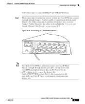
...to workstations, servers, routers, and Cisco IP Phones, connect a straight-through , twisted-pair cable. Figure 2-10 Connecting to a 10/100 Switch Port MODE SYSTEM RPS STATUS UTIL DUPLX SPEED 12 1X 2X 34 56 78 9 10 11 12 11X 12X 22001 Note The Catalyst 3524-PWR XL switch can connect to it. 78-...6456-04 Catalyst 3500 Series XL Hardware Installation Guide 2-19 The rear panel of the Cisco IP Phone might have...
...to workstations, servers, routers, and Cisco IP Phones, connect a straight-through , twisted-pair cable. Figure 2-10 Connecting to a 10/100 Switch Port MODE SYSTEM RPS STATUS UTIL DUPLX SPEED 12 1X 2X 34 56 78 9 10 11 12 11X 12X 22001 Note The Catalyst 3524-PWR XL switch can connect to it. 78-...6456-04 Catalyst 3500 Series XL Hardware Installation Guide 2-19 The rear panel of the Cisco IP Phone might have...
Installation Guide
Page 80
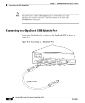
This takes about 30 seconds. Connecting to a GigaStack GBIC Module Port Connect the GigaStack cable connector to the GBIC Module Ports Chapter 2 Installing and Starting Up the Switch Note The port status is amber while Spanning Tree Protocol discovers the topology and searches for loops. The port LED then turns green. Connecting to the GigaStack GBIC as shown in Figure 2-12. Figure 2-12 Connecting to a GigaStack Port 32708 MODE 1394 SYSTEM RPS STATUS UTIL DUPLX SPEED 1 1 2 1 2 2 GigaStack cable 1394 2-22 Catalyst 3500 Series XL Hardware Installation Guide 78-6456-04
This takes about 30 seconds. Connecting to a GigaStack GBIC Module Port Connect the GigaStack cable connector to the GBIC Module Ports Chapter 2 Installing and Starting Up the Switch Note The port status is amber while Spanning Tree Protocol discovers the topology and searches for loops. The port LED then turns green. Connecting to the GigaStack GBIC as shown in Figure 2-12. Figure 2-12 Connecting to a GigaStack Port 32708 MODE 1394 SYSTEM RPS STATUS UTIL DUPLX SPEED 1 1 2 1 2 2 GigaStack cable 1394 2-22 Catalyst 3500 Series XL Hardware Installation Guide 78-6456-04
Installation Guide
Page 86
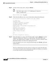
end ! You can be 1 to manage the switch. Enter cluster name: cls_name Step 12 Verify that the addresses are correct in the initial configuration displayed: The following configuration command script was created: ip subnet-zero interface VLAN1 ip...enable cls_name ! When you forget the password. 2-28 Catalyst 3500 Series XL Hardware Installation Guide 78-6456-04 The Cisco IOS Desktop Switching Software Configuration Guide describes how to set a password to protect the switch against unauthorized Telnet access and how to access the switch if you see the message "Press RETURN to get started...
end ! You can be 1 to manage the switch. Enter cluster name: cls_name Step 12 Verify that the addresses are correct in the initial configuration displayed: The following configuration command script was created: ip subnet-zero interface VLAN1 ip...enable cls_name ! When you forget the password. 2-28 Catalyst 3500 Series XL Hardware Installation Guide 78-6456-04 The Cisco IOS Desktop Switching Software Configuration Guide describes how to set a password to protect the switch against unauthorized Telnet access and how to access the switch if you see the message "Press RETURN to get started...

Installation Guide
Page 97
... X Technical Specifications 78-6456-04 Table A-1, Table A-2, and Table A-3, list the technical specifications for the Catalyst 3508G XL Switch Environmental Ranges Operating temperature Storage temperature Operating humidity Operating altitude Storage altitude Power Requirements AC input voltage DC input ... +12V @3A 82.2W 280 Btus per hour 12 lb (5.45 kg) 1.75 x 16 x 17.5 in. (4.45 x 40.46 x 44.45 cm) Catalyst 3500 Series XL Hardware Installation Guide A-1 Table A-1 Technical Specifications for the Catalyst 3500 series XL switches. Table A-4 lists the regulatory agency approvals.
... X Technical Specifications 78-6456-04 Table A-1, Table A-2, and Table A-3, list the technical specifications for the Catalyst 3508G XL Switch Environmental Ranges Operating temperature Storage temperature Operating humidity Operating altitude Storage altitude Power Requirements AC input voltage DC input ... +12V @3A 82.2W 280 Btus per hour 12 lb (5.45 kg) 1.75 x 16 x 17.5 in. (4.45 x 40.46 x 44.45 cm) Catalyst 3500 Series XL Hardware Installation Guide A-1 Table A-1 Technical Specifications for the Catalyst 3500 series XL switches. Table A-4 lists the regulatory agency approvals.

Installation Guide
Page 98
Appendix A Technical Specifications Table A-2 Technical Specifications for the Catalyst 3512, 3524, and 3548 XL Switches Catalyst 3512 XL Catalyst 3524 XL Catalyst 3548 XL Environmental Ranges Operating temperature 32 to 113°F (0 to 45°C) 32 to 113°F (0 to 45°C) 32 to 113°F (0 to 45°C) ... 171 Btus per hour 75W 256 Btus per hour 100W 342 Btus per hour Physical Dimensions Weight 10.25 lb (4.65 kg) 8.5 lb (3.86 kg) 12 lb (5.45 kg) Dimensions (H x 1.75 x 11.82 x 17.5 in. 1.75 x 11.82 x 17.5 in. 1.73 x 15.34 x 17.5 in D x W) (4.45 x 30.02 x 44.45 cm...
Appendix A Technical Specifications Table A-2 Technical Specifications for the Catalyst 3512, 3524, and 3548 XL Switches Catalyst 3512 XL Catalyst 3524 XL Catalyst 3548 XL Environmental Ranges Operating temperature 32 to 113°F (0 to 45°C) 32 to 113°F (0 to 45°C) 32 to 113°F (0 to 45°C) ... 171 Btus per hour 75W 256 Btus per hour 100W 342 Btus per hour Physical Dimensions Weight 10.25 lb (4.65 kg) 8.5 lb (3.86 kg) 12 lb (5.45 kg) Dimensions (H x 1.75 x 11.82 x 17.5 in. 1.75 x 11.82 x 17.5 in. 1.73 x 15.34 x 17.5 in D x W) (4.45 x 30.02 x 44.45 cm...

Installation Guide
Page 120
Jewelry Removal Warning Appendix C Translated Safety Warnings C-12 Catalyst 3500 Series XL Hardware Installation Guide 78-6456-04
Jewelry Removal Warning Appendix C Translated Safety Warnings C-12 Catalyst 3500 Series XL Hardware Installation Guide 78-6456-04