Installation Guide
Page 1
Catalyst 3500 Series XL Hardware Installation Guide August 2003 Corporate Headquarters Cisco Systems, Inc. 170 West Tasman Drive San Jose, CA 95134-1706 USA http://www.cisco.com Tel: 408 526-4000 800 553-NETS (6387) Fax: 408 526-4100 Customer Order Number: DOC-786456= Text Part Number: 78-6456-04
Catalyst 3500 Series XL Hardware Installation Guide August 2003 Corporate Headquarters Cisco Systems, Inc. 170 West Tasman Drive San Jose, CA 95134-1706 USA http://www.cisco.com Tel: 408 526-4000 800 553-NETS (6387) Fax: 408 526-4100 Customer Order Number: DOC-786456= Text Part Number: 78-6456-04

Installation Guide
Page 2
...or radio are designed to provide reasonable protection against harmful interference when the equipment is operated in part 15 of this equipment in a residential area is causing interference by Cisco Systems, Inc. Copyright © 1981, Regents of the University of the FCC rules. ... no guarantee that interference will be required to correct any interference to comply with Cisco's installation instructions, it was probably caused by the University of California, Berkeley (UCB) as part of UCB's public domain version of its peripheral devices. The following measures: •...
...or radio are designed to provide reasonable protection against harmful interference when the equipment is operated in part 15 of this equipment in a residential area is causing interference by Cisco Systems, Inc. Copyright © 1981, Regents of the University of the FCC rules. ... no guarantee that interference will be required to correct any interference to comply with Cisco's installation instructions, it was probably caused by the University of California, Berkeley (UCB) as part of UCB's public domain version of its peripheral devices. The following measures: •...

Installation Guide
Page 48
... 300, refer to the affected switch. Management Options Catalyst 3500 XL switches offer several management options: • Cisco Cluster Management Suite This suite is made up of the switches has experienced power failure and automatically sends power to the Cisco Redundant Power System 300 Hardware Installation Guide. Console Port You can order a kit (part number ACS-DSBUASYN=) containing...
... 300, refer to the affected switch. Management Options Catalyst 3500 XL switches offer several management options: • Cisco Cluster Management Suite This suite is made up of the switches has experienced power failure and automatically sends power to the Cisco Redundant Power System 300 Hardware Installation Guide. Console Port You can order a kit (part number ACS-DSBUASYN=) containing...
Installation Guide
Page 49
...Catalyst 3500 Series XL Hardware Installation Guide 1-25 The switch supports a comprehensive set configuration parameters and to send and receive data. If the switch is running platforms such as HP OpenView or SunNet Manager. Table 1-9 describes what can cause network performance to degrade and describes how you purchase separately, can be a standalone application or part... of the switch, to create dedicated network segments and interconnecting the segments through Fast Ethernet and Gigabit Ethernet connections. See the Cisco IOS Desktop Switching Command ...
...Catalyst 3500 Series XL Hardware Installation Guide 1-25 The switch supports a comprehensive set configuration parameters and to send and receive data. If the switch is running platforms such as HP OpenView or SunNet Manager. Table 1-9 describes what can cause network performance to degrade and describes how you purchase separately, can be a standalone application or part... of the switch, to create dedicated network segments and interconnecting the segments through Fast Ethernet and Gigabit Ethernet connections. See the Cisco IOS Desktop Switching Command ...
Installation Guide
Page 62
... voltages are made by using such interconnection methods unless the exposed metal parts are in the OFF position. Statement 1072 The following warning applies to the Catalyst 3508, 3512, 3524, and 3548 XL switches: Warning Attach only the Cisco RPS (model PWR600-AC-RPS) to the RPS receptacle. A restricted access area can exist on inline...
... voltages are made by using such interconnection methods unless the exposed metal parts are in the OFF position. Statement 1072 The following warning applies to the Catalyst 3508, 3512, 3524, and 3548 XL switches: Warning Attach only the Cisco RPS (model PWR600-AC-RPS) to the RPS receptacle. A restricted access area can exist on inline...

Installation Guide
Page 81
... a kit (part number ACS-DSBUASYN=) containing that your PC or terminal possible during the setup program. The terminal-emulation software-frequently a PC application such as Hyperterminal or Procomm Plus-makes communication between the switch and your PC- See the Cisco IOS Desktop Switching Software Configuration Guide for instructions. 78-6456-04 Catalyst 3500 Series XL Hardware...
... a kit (part number ACS-DSBUASYN=) containing that your PC or terminal possible during the setup program. The terminal-emulation software-frequently a PC application such as Hyperterminal or Procomm Plus-makes communication between the switch and your PC- See the Cisco IOS Desktop Switching Software Configuration Guide for instructions. 78-6456-04 Catalyst 3500 Series XL Hardware...

Installation Guide
Page 84
..., and press Return. You can order a kit (part number ACS-DSBUASYN=) containing that adapter from Cisco. Step 1 Step 2 Step 3 Step 4 Step 5 Step 6 Enter Y at the prompt: Continue with configuration dialog? [yes/no parity. Enter the switch IP address, and press Return: Enter IP address: ip_address...the default gateway: ip_address Enter a host name for the switch: Note Be sure the rollover cable is connecting a PC serial port to create an initial configuration for the switch, and press Return: 2-26 Catalyst 3500 Series XL Hardware Installation Guide 78-6456-04 Enter setup, and press...
..., and press Return. You can order a kit (part number ACS-DSBUASYN=) containing that adapter from Cisco. Step 1 Step 2 Step 3 Step 4 Step 5 Step 6 Enter Y at the prompt: Continue with configuration dialog? [yes/no parity. Enter the switch IP address, and press Return: Enter IP address: ip_address...the default gateway: ip_address Enter a host name for the switch: Note Be sure the rollover cable is connecting a PC serial port to create an initial configuration for the switch, and press Return: 2-26 Catalyst 3500 Series XL Hardware Installation Guide 78-6456-04 Enter setup, and press...

Installation Guide
Page 99
Appendix A Technical Specifications Table A-3 Technical Specifications for the Catalyst 3524-PWR XL Switch Environmental Ranges Operating temperature 32 to 113°F (0 to 45°C) Storage temperature -4 to 149°F (-10 to 65°C) Operating humidity 10 to... CE Marking 78-6456-04 Catalyst 3500 Series XL Hardware Installation Guide A-3 Table A-4 Catalyst 3500 Series XL Agency Approvals Safety EMC UL to UL 1950, Third Edition FCC Part 15 Class A c-UL to CAN/CSA 22.2 No. 950-95, Third Edition EN 55022 Class A (CISPR 22 Class A) TUV/GS to EN 60950 with Amendment A1-A4 ...
Appendix A Technical Specifications Table A-3 Technical Specifications for the Catalyst 3524-PWR XL Switch Environmental Ranges Operating temperature 32 to 113°F (0 to 45°C) Storage temperature -4 to 149°F (-10 to 65°C) Operating humidity 10 to... CE Marking 78-6456-04 Catalyst 3500 Series XL Hardware Installation Guide A-3 Table A-4 Catalyst 3500 Series XL Agency Approvals Safety EMC UL to UL 1950, Third Edition FCC Part 15 Class A c-UL to CAN/CSA 22.2 No. 950-95, Third Edition EN 55022 Class A (CISPR 22 Class A) TUV/GS to EN 60950 with Amendment A1-A4 ...

Installation Guide
Page 103
... order a kit (part number ACS-DSBUASYN=) containing that adapter from Cisco. You need to provide a RJ-45-to-DB-25 female DTE adapter if you want to connect the switch console port to a console PC. For console port and adapter pinout information, see Table B-1 and Table B-2. 78-6456-04 Catalyst 3500 Series XL Hardware Installation... proprietary connectors, as shown in Table B-1 and Table B-2. Figure B-3 GigaStack Connector 22084 The GigaStack GBIC cables are used to connect the console port of the switch to a terminal.
... order a kit (part number ACS-DSBUASYN=) containing that adapter from Cisco. You need to provide a RJ-45-to-DB-25 female DTE adapter if you want to connect the switch console port to a console PC. For console port and adapter pinout information, see Table B-1 and Table B-2. 78-6456-04 Catalyst 3500 Series XL Hardware Installation... proprietary connectors, as shown in Table B-1 and Table B-2. Figure B-3 GigaStack Connector 22084 The GigaStack GBIC cables are used to connect the console port of the switch to a terminal.
Installation Guide
Page 107
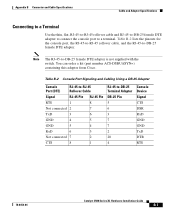
...-25 Pin 5 6 3 7 7 2 20 4 Console Device Signal CTS DSR RxD GND GND TxD DTR RTS 78-6456-04 Catalyst 3500 Series XL Hardware Installation Guide B-7 You can order a kit (part number ACS-DSBUASYN=) containing this adapter from Cisco. Table B-2 Console Port Signaling and Cabling Using a DB-25 Adapter Console Port (DTE) RJ-45-to-RJ... and RJ-45-to-DB-25 female DTE adapter to connect the console port to -DB-25 female DTE adapter is not supplied with the switch.
...-25 Pin 5 6 3 7 7 2 20 4 Console Device Signal CTS DSR RxD GND GND TxD DTR RTS 78-6456-04 Catalyst 3500 Series XL Hardware Installation Guide B-7 You can order a kit (part number ACS-DSBUASYN=) containing this adapter from Cisco. Table B-2 Console Port Signaling and Cabling Using a DB-25 Adapter Console Port (DTE) RJ-45-to-RJ... and RJ-45-to-DB-25 female DTE adapter to connect the console port to -DB-25 female DTE adapter is not supplied with the switch.