
Installation Guide
Page 7
... Switch 2-10 Attaching the Brackets to the Switch 2-11 Mounting the Switch in a Rack 2-13 Attaching the Optional Cable Guide 2-13 Installing the Switch on a Wall 2-15 Attaching the Brackets to the Switch 2-15 Attaching the Switch to a Wall 2-16 Installing the Switch on a Table or Shelf 2-17 Powering On the Switch and... Module Port 2-21 Connecting to a GigaStack GBIC Module Port 2-22 Connecting a PC or Terminal to the Console Port 2-23 Assigning Switch Information 2-24 Using the Setup Program 2-25 Using BOOTP 2-29 Default Configuration Settings 2-29 Where to Go Next 2-31 Troubleshooting 3-1 ...
... Switch 2-10 Attaching the Brackets to the Switch 2-11 Mounting the Switch in a Rack 2-13 Attaching the Optional Cable Guide 2-13 Installing the Switch on a Wall 2-15 Attaching the Brackets to the Switch 2-15 Attaching the Switch to a Wall 2-16 Installing the Switch on a Table or Shelf 2-17 Powering On the Switch and... Module Port 2-21 Connecting to a GigaStack GBIC Module Port 2-22 Connecting a PC or Terminal to the Console Port 2-23 Assigning Switch Information 2-24 Using the Setup Program 2-25 Using BOOTP 2-29 Default Configuration Settings 2-29 Where to Go Next 2-31 Troubleshooting 3-1 ...

Installation Guide
Page 12
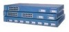
...and Starting Up the Switch," contains the procedures for the switches and the regulatory agency approvals. Appendix A, "Technical Specifications," lists the physical and environmental specifications for installing a switch on a rack, wall, table, or ...switch initial configuration. Conventions This guide uses the following chapters: Chapter 1, "Product Overview," is a physical and functional overview of the problems that can be installed suggest possible deployment strategies. It describes the switch ports, the standards they support, and the switch LEDs. Catalyst 3500 Series XL...
...and Starting Up the Switch," contains the procedures for the switches and the regulatory agency approvals. Appendix A, "Technical Specifications," lists the physical and environmental specifications for installing a switch on a rack, wall, table, or ...switch initial configuration. Conventions This guide uses the following chapters: Chapter 1, "Product Overview," is a physical and functional overview of the problems that can be installed suggest possible deployment strategies. It describes the switch ports, the standards they support, and the switch LEDs. Catalyst 3500 Series XL...

Installation Guide
Page 73
... the second bracket to the switch. Figure 2-8 shows how to attach the brackets to one side of the bracket to the opposite side. Figure 2-8 Attaching Brackets for Wall-Mounting 30060 DC INPUTS SPECIFIED IFNOMRARNEUMAOL.T+E3P.3OVW***E@R1S4UAP, PLY DC INPUT +12V***@3A For vertical wall-mounting Phillips flat-head screws 78-6456-04 Catalyst 3500 Series XL Hardware Installation...
... the second bracket to the switch. Figure 2-8 shows how to attach the brackets to one side of the bracket to the opposite side. Figure 2-8 Attaching Brackets for Wall-Mounting 30060 DC INPUTS SPECIFIED IFNOMRARNEUMAOL.T+E3P.3OVW***E@R1S4UAP, PLY DC INPUT +12V***@3A For vertical wall-mounting Phillips flat-head screws 78-6456-04 Catalyst 3500 Series XL Hardware Installation...
Installation Guide
Page 156
...procedures 2-24 IP setup 2-26 J jewelry removal warning C-10 L LAN-to-phone jack 2-19 LEDs Catalyst 3508G XL front panel 1-11 Catalyst 3512 and 3524 XL front panel 1-12 Catalyst 3548 XL front panel 1-14 color meanings 1-18 duplex 1-17, 1-18 half-duplex 1-17, 1-18 interpreting 1-... M management features and defaults 2-30 Mode button 1-11, 1-16 Mode label (on Catalyst 3548 XL only) 1-16 models, switch 1-2 mounting, table or desk 2-17 mounting brackets 2-9 attaching 2-11, 2-15 rack-mount 2-13 wall-mount 2-16 N network configuration examples 1-25 network redundancy values 2-30 noise, electrical 2-8...
...procedures 2-24 IP setup 2-26 J jewelry removal warning C-10 L LAN-to-phone jack 2-19 LEDs Catalyst 3508G XL front panel 1-11 Catalyst 3512 and 3524 XL front panel 1-12 Catalyst 3548 XL front panel 1-14 color meanings 1-18 duplex 1-17, 1-18 half-duplex 1-17, 1-18 interpreting 1-... M management features and defaults 2-30 Mode button 1-11, 1-16 Mode label (on Catalyst 3548 XL only) 1-16 models, switch 1-2 mounting, table or desk 2-17 mounting brackets 2-9 attaching 2-11, 2-15 rack-mount 2-13 wall-mount 2-16 N network configuration examples 1-25 network redundancy values 2-30 noise, electrical 2-8...