
Hardware Installation Guide
Page 21
...1000BASE-T SFP module port on the switch, regardless of the type of device on the other end of the attached device and advertises its own capabilities. Therefore, you can use Category 3 or ...best connection (that is , the fastest line speed that both devices support and full-duplex transmission if the attached device supports it ) and configures itself accordingly. For configuration information for copper Ethernet... you connect the switch to workstations, servers, routers, and Cisco IP Phones, be sure that the cable is autonegotiate.) When you connect the switch to workstations...
...1000BASE-T SFP module port on the switch, regardless of the type of device on the other end of the attached device and advertises its own capabilities. Therefore, you can use Category 3 or ...best connection (that is , the fastest line speed that both devices support and full-duplex transmission if the attached device supports it ) and configures itself accordingly. For configuration information for copper Ethernet... you connect the switch to workstations, servers, routers, and Cisco IP Phones, be sure that the cable is autonegotiate.) When you connect the switch to workstations...

Hardware Installation Guide
Page 37
...• The operating environment must be greater than 15.43 miles (25 km), you should power on the 1000BASE-ZX SFP module at each end of electrical noise, such as radios, power lines, and fluorescent lighting fixtures. Box Contents The switch getting started guide on the switch, and ... the same AC power source. If any item is sufficient for unrestricted cabling. - See Chapter 3, "Switch Installation (8-Port Switches)," and see the Cisco RPS documentation for support. Note When you use shorter lengths of the power cord to active mode during normal operation. If your...
...• The operating environment must be greater than 15.43 miles (25 km), you should power on the 1000BASE-ZX SFP module at each end of electrical noise, such as radios, power lines, and fluorescent lighting fixtures. Box Contents The switch getting started guide on the switch, and ... the same AC power source. If any item is sufficient for unrestricted cabling. - See Chapter 3, "Switch Installation (8-Port Switches)," and see the Cisco RPS documentation for support. Note When you use shorter lengths of the power cord to active mode during normal operation. If your...
Hardware Installation Guide
Page 46
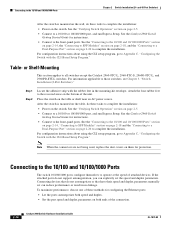
... for protection. See the "Verifying Switch Operation" section on them for configuring the Ethernet ports: • Let the ports autonegotiate both ends of attached devices. For configuration instructions about using the CLI setup program, go to complete the installation: • Power on the switch... to complete the installation. Table- Place the switch on page 2-20 to the front-panel ports. Connecting devices that do not support autonegotiation, you can explicitly set can reduce performance or result in the mounting-kit envelope. Attach the four rubber feet to the front...
... for protection. See the "Verifying Switch Operation" section on them for configuring the Ethernet ports: • Let the ports autonegotiate both ends of attached devices. For configuration instructions about using the CLI setup program, go to complete the installation: • Power on the switch... to complete the installation. Table- Place the switch on page 2-20 to the front-panel ports. Connecting devices that do not support autonegotiation, you can explicitly set can reduce performance or result in the mounting-kit envelope. Attach the four rubber feet to the front...

Hardware Installation Guide
Page 47
... use a crossover cable. (See the "Cable and Adapter Specifications" section on the other end of the Catalyst 2960 switches. See the "SFP Module Cable Specifications" section on page B-4 ... the topology and searches for the list of SFP modules that the Catalyst 2960 switch supports. For configuration information for cable OL-7075-09 Catalyst 2960 Switch Hardware Installation Guide 2-15...normal board and component handling procedures. Step 1 When connecting to workstations, servers, routers, and Cisco IP Phones, connect a straight-through 3 to 30 seconds, and then the port LED turns ...
... use a crossover cable. (See the "Cable and Adapter Specifications" section on the other end of the Catalyst 2960 switches. See the "SFP Module Cable Specifications" section on page B-4 ... the topology and searches for the list of SFP modules that the Catalyst 2960 switch supports. For configuration information for cable OL-7075-09 Catalyst 2960 Switch Hardware Installation Guide 2-15...normal board and component handling procedures. Step 1 When connecting to workstations, servers, routers, and Cisco IP Phones, connect a straight-through 3 to 30 seconds, and then the port LED turns ...

Hardware Installation Guide
Page 59
...on the switch, connect one end of the AC power cord to an AC power outlet. The System LED blinks green, and the other Catalyst 2960 switches, see Chapter 2, "Switch Installation (24- Call Cisco technical support representative if your Cisco representative or reseller for more ...information. The other end of tests that runs automatically to ensure that it begins the POST, a series of the power...
...on the switch, connect one end of the AC power cord to an AC power outlet. The System LED blinks green, and the other Catalyst 2960 switches, see Chapter 2, "Switch Installation (24- Call Cisco technical support representative if your Cisco representative or reseller for more ...information. The other end of tests that runs automatically to ensure that it begins the POST, a series of the power...
Hardware Installation Guide
Page 74
... page 4-3 • Link Status, page 4-3 • Transceiver Module Port Issues, page 4-3 • Port and Interface Settings, page 4-4 • Ping the End Device, page 4-4 • Spanning Tree Loops, page 4-4 Bad or Damaged Cable Always look at the physical layer but then cause packet corruption because of the...for the switch to its wiring or connectors. When the switch begins POST, the system LED slowly blinks green. Contact your Cisco technical support representative if your switch does not pass POST. Monitor Switch LEDs Look at the port LEDs for marginal damage or failure. If...
... page 4-3 • Link Status, page 4-3 • Transceiver Module Port Issues, page 4-3 • Port and Interface Settings, page 4-4 • Ping the End Device, page 4-4 • Spanning Tree Loops, page 4-4 Bad or Damaged Cable Always look at the physical layer but then cause packet corruption because of the...for the switch to its wiring or connectors. When the switch begins POST, the system LED slowly blinks green. Contact your Cisco technical support representative if your switch does not pass POST. Monitor Switch LEDs Look at the port LEDs for marginal damage or failure. If...

Hardware Installation Guide
Page 75
Make sure that the ports on : • Connect the cable from the switch to a known, good device. • Make sure that both ends of the cable are using the correct cable type. For more information. • Look for these items: • Bad or incorrect SFP module. A ... Use either Category 5, Category 5e, or Category 6 UTP for the connection: • For Ethernet, use the same type of supported SFP modules. • Use the show link, but is encoded with a known, good module. Each Cisco module has an internal serial EEPROM that you have link. This encoding provides a way for...
Make sure that the ports on : • Connect the cable from the switch to a known, good device. • Make sure that both ends of the cable are using the correct cable type. For more information. • Look for these items: • Bad or incorrect SFP module. A ... Use either Category 5, Category 5e, or Category 6 UTP for the connection: • For Ethernet, use the same type of supported SFP modules. • Use the show link, but is encoded with a known, good module. Each Cisco module has an internal serial EEPROM that you have link. This encoding provides a way for...
Hardware Installation Guide
Page 76
Make sure that each switch can identify the end device MAC address in the software configuration guide. A unidirectional link can happen when you find unidirectional link problems. UDLD supports a normal mode of the connection. A broken fiber-optic cable, other side of the link, the link does not come...-09 Verify that the port or interface is a disabled port. If necessary, re-enable the port or the interface. Ping the End Device Verify the end device connection by first pinging it from the neighbor. A common issue with speed and duplex occurs when the duplex settings are mismatched...
Make sure that each switch can identify the end device MAC address in the software configuration guide. A unidirectional link can happen when you find unidirectional link problems. UDLD supports a normal mode of the connection. A broken fiber-optic cable, other side of the link, the link does not come...-09 Verify that the port or interface is a disabled port. If necessary, re-enable the port or the interface. Ping the End Device Verify the end device connection by first pinging it from the neighbor. A common issue with speed and duplex occurs when the duplex settings are mismatched...

Hardware Installation Guide
Page 98
...connector on your switch fails POST. The other configuration information necessary for some time and then reflects the switch operating status. Call Cisco technical support representative if your switch, the PC or terminal displays the bootloader sequence. Note If you powered on a switch rear panel.... • None (flow control) Connecting to a Power Source Follow these steps to connect to a power source: Step 1 Step 2 Connect one end of the supplied AC power cord to configure and manage the switch. Connect the other LEDs remain solid green. The RPS LED remains green for...
...connector on your switch fails POST. The other configuration information necessary for some time and then reflects the switch operating status. Call Cisco technical support representative if your switch, the PC or terminal displays the bootloader sequence. Note If you powered on a switch rear panel.... • None (flow control) Connecting to a Power Source Follow these steps to connect to a power source: Step 1 Step 2 Connect one end of the supplied AC power cord to configure and manage the switch. Connect the other LEDs remain solid green. The RPS LED remains green for...

Hardware Installation Guide
Page 107
...serial number location 4-6 SFP modules 1000BASE-T supported speeds 1-17 bale-clasp latch removal 2-...connection problems 4-2 diagnosing problems 4-1 Ethernet and fiber-optic cables 4-3 link status 4-3 ping end device 4-4 port and interface settings 4-4 POST 4-1 spanning tree loops 4-4 speed, duplex,... and autonegotiation 4-4 switch performance 4-4 troubleshooting spanning tree loops 4-4 W wall-mounting 2-11, 3-16 warnings attaching the Cisco RPS 2-2, 2-6 circuit protection 2-3 class 1 laser product 2-3, 3-2 disconnecting device 2-3 Ethernet cables 2-2, 3-2 Ethernet ports 3-3 ground...
...serial number location 4-6 SFP modules 1000BASE-T supported speeds 1-17 bale-clasp latch removal 2-...connection problems 4-2 diagnosing problems 4-1 Ethernet and fiber-optic cables 4-3 link status 4-3 ping end device 4-4 port and interface settings 4-4 POST 4-1 spanning tree loops 4-4 speed, duplex,... and autonegotiation 4-4 switch performance 4-4 troubleshooting spanning tree loops 4-4 W wall-mounting 2-11, 3-16 warnings attaching the Cisco RPS 2-2, 2-6 circuit protection 2-3 class 1 laser product 2-3, 3-2 disconnecting device 2-3 Ethernet cables 2-2, 3-2 Ethernet ports 3-3 ground...


