
Hardware Installation Guide
Page 2
... to comply with the specifications in a commercial environment. All rights reserved. Modifying the equipment without Cisco's written authorization may radiate radio-frequency energy. If the interference stops, it off. CCDE, CCENT, CCSI, Cisco Eos, Cisco Explorer, Cisco HealthPresence, Cisco IronPort, the Cisco logo, Cisco Nurse Connect, Cisco Pulse, Cisco SensorBase, Cisco StackPower, Cisco StadiumVision, Cisco TelePresence, Cisco TrustSec, Cisco Unified Computing System, Cisco WebEx, DCE, Flip...
... to comply with the specifications in a commercial environment. All rights reserved. Modifying the equipment without Cisco's written authorization may radiate radio-frequency energy. If the interference stops, it off. CCDE, CCENT, CCSI, Cisco Eos, Cisco Explorer, Cisco HealthPresence, Cisco IronPort, the Cisco logo, Cisco Nurse Connect, Cisco Pulse, Cisco SensorBase, Cisco StackPower, Cisco StadiumVision, Cisco TelePresence, Cisco TrustSec, Cisco Unified Computing System, Cisco WebEx, DCE, Flip...

Hardware Installation Guide
Page 5
... Switch Performance 4-4 Speed, Duplex, and Autonegotiation 4-4 Autonegotiation and NIC Cards 4-5 Cabling Distance 4-5 Clearing the Switch IP Address and Configuration 4-5 Locating the Switch Serial Number 4-6 Technical Specifications A-1 Connector and Cable Specifications B-1 Connector Specifications B-1 10/100/1000 Ports B-1 Connecting to 1000BASE-T Devices B-2 SFP Module Ports B-3 Dual-Purpose Ports B-3 Catalyst 2960 Switch Hardware Installation Guide v
... Switch Performance 4-4 Speed, Duplex, and Autonegotiation 4-4 Autonegotiation and NIC Cards 4-5 Cabling Distance 4-5 Clearing the Switch IP Address and Configuration 4-5 Locating the Switch Serial Number 4-6 Technical Specifications A-1 Connector and Cable Specifications B-1 Connector Specifications B-1 10/100/1000 Ports B-1 Connecting to 1000BASE-T Devices B-2 SFP Module Ports B-3 Dual-Purpose Ports B-3 Catalyst 2960 Switch Hardware Installation Guide v

Hardware Installation Guide
Page 6
Contents C A P P E N D I X INDEX Console Port B-4 Cable and Adapter Specifications B-4 SFP Module Cable Specifications B-4 Two Twisted-Pair Cable Pinouts B-6 Four Twisted-Pair Cable Pinouts for 1000BASE-T Ports B-6 Crossover Cable and Adapter Pinouts B-7 Identifying a Crossover Cable B-7 Adapter Pinouts B-8 Configuring the ...
Contents C A P P E N D I X INDEX Console Port B-4 Cable and Adapter Specifications B-4 SFP Module Cable Specifications B-4 Two Twisted-Pair Cable Pinouts B-6 Four Twisted-Pair Cable Pinouts for 1000BASE-T Ports B-6 Crossover Cable and Adapter Pinouts B-7 Identifying a Crossover Cable B-7 Adapter Pinouts B-8 Configuring the ...

Hardware Installation Guide
Page 13
...• 100BASE-FX • 100BASE-LX The Catalyst 2960-24PC-L, 2960-24PC-S, 2960-24LC-S, 2960-24TC-L, 2960-48TC-L, 2960-48PST-L, 2960-48PST-S, 2960G-24TC-L, and 2960G-48TC-L switches support all the SFP modules. These switches do not support the 1000BASE-T or GLC-GE...and 100BASE-FX SFP modules. Chapter 1 Product Overview Features These are supported on specific switches, see the Cisco Gigabit Ethernet Transceiver Modules Compatibility Matrix at this Cisco.com URL: http://www.cisco.com/en/US/docs/interfaces_modules/transceiver_modules/compatibility/matrix/ OL_6981.html The 1000BASE-T SFP...
...• 100BASE-FX • 100BASE-LX The Catalyst 2960-24PC-L, 2960-24PC-S, 2960-24LC-S, 2960-24TC-L, 2960-48TC-L, 2960-48PST-L, 2960-48PST-S, 2960G-24TC-L, and 2960G-48TC-L switches support all the SFP modules. These switches do not support the 1000BASE-T or GLC-GE...and 100BASE-FX SFP modules. Chapter 1 Product Overview Features These are supported on specific switches, see the Cisco Gigabit Ethernet Transceiver Modules Compatibility Matrix at this Cisco.com URL: http://www.cisco.com/en/US/docs/interfaces_modules/transceiver_modules/compatibility/matrix/ OL_6981.html The 1000BASE-T SFP...

Hardware Installation Guide
Page 21
... 4 cables. When the port is set these ports for speed and duplex autonegotiation. When you connect the switch to workstations, servers, routers, and Cisco IP Phones, be within 328 feet (100 meters). 100BASE-TX and 1000BASE-T traffic requires a Category 5 or higher cable. 10BASE-T traffic can also...the cable is a straight-through cable for connections to operate at 10, 100, or 1000 Mb/s in Appendix B, "Connector and Cable Specifications." Pinouts for the cables are described in full-duplex or half-duplex mode. For configuration information for this feature, see the switch software ...
... 4 cables. When the port is set these ports for speed and duplex autonegotiation. When you connect the switch to workstations, servers, routers, and Cisco IP Phones, be within 328 feet (100 meters). 100BASE-TX and 1000BASE-T traffic requires a Category 5 or higher cable. 10BASE-T traffic can also...the cable is a straight-through cable for connections to operate at 10, 100, or 1000 Mb/s in Appendix B, "Connector and Cable Specifications." Pinouts for the cables are described in full-duplex or half-duplex mode. For configuration information for this feature, see the switch software ...

Hardware Installation Guide
Page 23
... connections to establish fiber-optic connections. Dual-Purpose Port You can order it from these SFP modules, see Appendix B, "Connector and Cable Specifications." The dual front ends are field-replaceable, providing the uplink interfaces when you insert an SFP module. Through an external AC power adapter... to connect to a fiber-optic SFP module. The port LED is not included with the switch, but you can receive power from your Cisco representative. (See Figure 1-22.) OL-7075-09 Catalyst 2960 Switch Hardware Installation Guide 1-13 This external power adapter (PWR-A=) is on the...
... connections to establish fiber-optic connections. Dual-Purpose Port You can order it from these SFP modules, see Appendix B, "Connector and Cable Specifications." The dual front ends are field-replaceable, providing the uplink interfaces when you insert an SFP module. Through an external AC power adapter... to connect to a fiber-optic SFP module. The port LED is not included with the switch, but you can receive power from your Cisco representative. (See Figure 1-22.) OL-7075-09 Catalyst 2960 Switch Hardware Installation Guide 1-13 This external power adapter (PWR-A=) is on the...

Hardware Installation Guide
Page 31
... 8-port switches have security slots on a left and right side panels. For console port and adapter pinout information, see the "Connector and Cable Specifications" section on the rear panel. Console Port You can connect the switch to a PC by the RPS • Obtain status reports for the ...slot OL-7075-09 Catalyst 2960 Switch Hardware Installation Guide 1-21 You can install an optional cable lock, such as the type that adapter from Cisco. It automatically senses when the internal power supply of a connected switch fails and provides power to -DB-25 female DTE adapter. Chapter 1...
... 8-port switches have security slots on a left and right side panels. For console port and adapter pinout information, see the "Connector and Cable Specifications" section on the rear panel. Console Port You can connect the switch to a PC by the RPS • Obtain status reports for the ...slot OL-7075-09 Catalyst 2960 Switch Hardware Installation Guide 1-21 You can install an optional cable lock, such as the type that adapter from Cisco. It automatically senses when the internal power supply of a connected switch fails and provides power to -DB-25 female DTE adapter. Chapter 1...

Hardware Installation Guide
Page 36
... can use of the hazard. Catalyst 2960 switch SFP ports can be sure to all Catalyst 2960 switches except for Particulate Matter Cisco Ethernet switches are made aware of a special tool, lock and key or other particles, causing contaminant buildup inside . Statement 1046... such as metal flakes from construction activities). Statement 1072 Warning No user-serviceable parts inside the chassis, which lists the cable specifications for 1000BASE-X and 100BASE-X SFP modules for Installation Chapter 2 Switch Installation (24- These standards provide guidelines for acceptable working ...
... can use of the hazard. Catalyst 2960 switch SFP ports can be sure to all Catalyst 2960 switches except for Particulate Matter Cisco Ethernet switches are made aware of a special tool, lock and key or other particles, causing contaminant buildup inside . Statement 1046... such as metal flakes from construction activities). Statement 1072 Warning No user-serviceable parts inside the chassis, which lists the cable specifications for 1000BASE-X and 100BASE-X SFP modules for Installation Chapter 2 Switch Installation (24- These standards provide guidelines for acceptable working ...

Hardware Installation Guide
Page 37
...25 km), you install the switch in a closed or multirack assembly, the temperature around it might be within the ranges listed in Appendix A, "Technical Specifications." • Clearance to insert an inline optical attenuator in standby mode. The rear-panel power connector is within reach of an AC power receptacle. •... to the same AC power source. To power on the switch, connect one end of the AC power cord to the AC power connector on Cisco.com describes the box contents. Note When you might damage the cables. • Airflow around the unit does not exceed 113°F (45&#...
...25 km), you install the switch in a closed or multirack assembly, the temperature around it might be within the ranges listed in Appendix A, "Technical Specifications." • Clearance to insert an inline optical attenuator in standby mode. The rear-panel power connector is within reach of an AC power receptacle. •... to the same AC power source. To power on the switch, connect one end of the AC power cord to the AC power connector on Cisco.com describes the box contents. Note When you might damage the cables. • Airflow around the unit does not exceed 113°F (45&#...

Hardware Installation Guide
Page 38
... in the "Installing the Switch" section on page 2-6. Warning To prevent bodily injury when mounting or servicing this section might not show your specific switch; POST lasts approximately 1 minute. When the switch begins POST, the System, RPS, Status, Duplex, and Speed LEDs turn off and..., or on , it is provided with stabilizing devices, install the stabilizers before mounting or servicing the unit in the rack. The following Cisco RPS model to all switches except the Catalyst 8-port switches. LEDs can blink during the test. For information applicable to ensure that the system...
... in the "Installing the Switch" section on page 2-6. Warning To prevent bodily injury when mounting or servicing this section might not show your specific switch; POST lasts approximately 1 minute. When the switch begins POST, the System, RPS, Status, Duplex, and Speed LEDs turn off and..., or on , it is provided with stabilizing devices, install the stabilizers before mounting or servicing the unit in the rack. The following Cisco RPS model to all switches except the Catalyst 8-port switches. LEDs can blink during the test. For information applicable to ensure that the system...

Hardware Installation Guide
Page 47
...guide or the switch command reference. Refer to cabling problems. Reconfigure and reboot the connected device if necessary. See the "SFP Module Cable Specifications" section on the other end of SFP modules. Figure 2-13 Connecting to an RJ-45 connector on page B-4 for the list of... enabled by default. This can use a twisted four-pair, Category 5 or higher cable. Step 1 When connecting to workstations, servers, routers, and Cisco IP Phones, connect a straight-through 3 to 30 seconds, and then the port LED turns green. and 48-Port Switches) Installing and Removing SFP Modules...
...guide or the switch command reference. Refer to cabling problems. Reconfigure and reboot the connected device if necessary. See the "SFP Module Cable Specifications" section on the other end of SFP modules. Figure 2-13 Connecting to an RJ-45 connector on page B-4 for the list of... enabled by default. This can use a twisted four-pair, Category 5 or higher cable. Step 1 When connecting to workstations, servers, routers, and Cisco IP Phones, connect a straight-through 3 to 30 seconds, and then the port LED turns green. and 48-Port Switches) Installing and Removing SFP Modules...
Hardware Installation Guide
Page 50
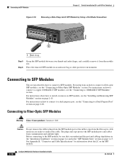
... Slots" section on how to connect to fiber-optic SFP modules, see the "Connecting to Fiber-Optic SFP Modules" section. See Appendix B, "Connector and Cable Specifications" for information about how to the SFP module, be sure that you are ready to SFP modules. For instructions on page 1-13. For instructions on...
... Slots" section on how to connect to fiber-optic SFP modules, see the "Connecting to Fiber-Optic SFP Modules" section. See Appendix B, "Connector and Cable Specifications" for information about how to the SFP module, be sure that you are ready to SFP modules. For instructions on page 1-13. For instructions on...

Hardware Installation Guide
Page 55
... information applicable to the Catalyst 2960-8TC-S, Catalyst 2960-8TC-L, Catalyst 2960G-8TC-L, and Catalyst 2960PD-8TT-L switches. The installation information in this chapter is specific to the other Catalyst 2960 switches, see Chapter 2, "Switch Installation (24- Preparing for Installation This section covers these topics: • Warnings, page 3-1 • Installation Guidelines...
... information applicable to the Catalyst 2960-8TC-S, Catalyst 2960-8TC-L, Catalyst 2960G-8TC-L, and Catalyst 2960PD-8TT-L switches. The installation information in this chapter is specific to the other Catalyst 2960 switches, see Chapter 2, "Switch Installation (24- Preparing for Installation This section covers these topics: • Warnings, page 3-1 • Installation Guidelines...

Hardware Installation Guide
Page 57
...are uncertain that exceeds normal room temperature (such as in a closet, in a cabinet, or in a closed environment or in Appendix A, "Technical Specifications." • Airflow around the unit does not exceed 113°F (45°C). OL-7075-09 Catalyst 2960 Switch Hardware Installation Guide 3-3 and ... 1040. Do not open. Warning For connections outside the building where the equipment is in an environment that suitable grounding is specific to all national laws and regulations. If the switch is installed in the absence of this product should be unrestricted. Statement 1024...
...are uncertain that exceeds normal room temperature (such as in a closet, in a cabinet, or in a closed environment or in Appendix A, "Technical Specifications." • Airflow around the unit does not exceed 113°F (45°C). OL-7075-09 Catalyst 2960 Switch Hardware Installation Guide 3-3 and ... 1040. Do not open. Warning For connections outside the building where the equipment is in an environment that suitable grounding is specific to all national laws and regulations. If the switch is installed in the absence of this product should be unrestricted. Statement 1024...

Hardware Installation Guide
Page 58
... overloading the receiver. and 48-Port Switches)." To order a cable guard, contact your Cisco representative and use these conditions - You can use shorter lengths of the link. Catalyst ...each other. • Allow at each switch in Table B-1 on page B-5, which lists the cable specifications for 1000BASE-X and 100BASE-X small form-factor (SFP) modules available for unrestricted cabling. - When you ... Catalyst 2960-8TC-L, 2960-8TC-S, and 2960PD-8TT-L switches cable guard part number: CBLGRD-C2960-8TC= • Catalyst 2960G-8TC-L switch cable guard part number: CBLGRD-C2960G-8TC= The...
... overloading the receiver. and 48-Port Switches)." To order a cable guard, contact your Cisco representative and use these conditions - You can use shorter lengths of the link. Catalyst ...each other. • Allow at each switch in Table B-1 on page B-5, which lists the cable specifications for 1000BASE-X and 100BASE-X small form-factor (SFP) modules available for unrestricted cabling. - When you ... Catalyst 2960-8TC-L, 2960-8TC-S, and 2960PD-8TT-L switches cable guard part number: CBLGRD-C2960-8TC= • Catalyst 2960G-8TC-L switch cable guard part number: CBLGRD-C2960G-8TC= The...

Hardware Installation Guide
Page 59
.... If a switch fails POST, the System LED turns amber. After a successful POST, disconnect the power cord from Cisco. Installing the Switch This section is RCKMNT-19-CMPCT=. If you want to connect a terminal to the switch console... that adapter from an upstream PoE switch. See the "Power Input Port (Catalyst 2960PD-8TT-L Switch)" section on Cisco.com describes the box contents. LEDs can order a kit containing the 19-inch rack-mounting brackets and hardware from the... damaged, contact your switch fails POST. The kit part number is specific to an AC power adapter on the rear panel.
.... If a switch fails POST, the System LED turns amber. After a successful POST, disconnect the power cord from Cisco. Installing the Switch This section is RCKMNT-19-CMPCT=. If you want to connect a terminal to the switch console... that adapter from an upstream PoE switch. See the "Power Input Port (Catalyst 2960PD-8TT-L Switch)" section on Cisco.com describes the box contents. LEDs can order a kit containing the 19-inch rack-mounting brackets and hardware from the... damaged, contact your switch fails POST. The kit part number is specific to an AC power adapter on the rear panel.

Hardware Installation Guide
Page 60
... C, "Configuring the Switch with the rubber feet in the accessory kit. Connect to the front-panel ports. and 48-Port Switches)." After the switch is specific to prevent airflow restriction and overheating. See the "Connecting to the 10/100 and 10/100/1000 Ports" section on page 2-14, the "Connecting to...
... C, "Configuring the Switch with the rubber feet in the accessory kit. Connect to the front-panel ports. and 48-Port Switches)." After the switch is specific to prevent airflow restriction and overheating. See the "Connecting to the 10/100 and 10/100/1000 Ports" section on page 2-14, the "Connecting to...
Hardware Installation Guide
Page 61
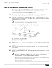
... in Figure 3-2. Do not stack switches or place switches side-by -side slots face the front of the desk or shelf after the switch is specific to make sure that the two side-by -side unless they touch the top of clearance from the desk or shelf. Chapter 3 Switch Installation (8-Port...
... in Figure 3-2. Do not stack switches or place switches side-by -side slots face the front of the desk or shelf after the switch is specific to make sure that the two side-by -side unless they touch the top of clearance from the desk or shelf. Chapter 3 Switch Installation (8-Port...
Hardware Installation Guide
Page 62
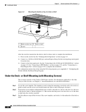
... the screws are installed under the desk or shelf with Mounting Screws) This section is also used to align the mounting screw holes and is specific to Appendix C, "Configuring the Switch with the CLI-Based Setup Program." This ensures that the two side-by-side slots face the front of the...
... the screws are installed under the desk or shelf with Mounting Screws) This section is also used to align the mounting screw holes and is specific to Appendix C, "Configuring the Switch with the CLI-Based Setup Program." This ensures that the two side-by-side slots face the front of the...
Hardware Installation Guide
Page 65
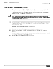
... how to the other Catalyst 2960 switches, see Chapter 2, "Switch Installation (24- OL-7075-09 Catalyst 2960 Switch Hardware Installation Guide 3-11 The template is specific to the system. Follow the steps in Figure 3-5. According to safety regulations, wall-mount the switch with the front panel facing down to prevent airflow...
... how to the other Catalyst 2960 switches, see Chapter 2, "Switch Installation (24- OL-7075-09 Catalyst 2960 Switch Hardware Installation Guide 3-11 The template is specific to the system. Follow the steps in Figure 3-5. According to safety regulations, wall-mount the switch with the front panel facing down to prevent airflow...
