Installation Guide
Page 10
In addition, it is unique to the Cisco 700 series router. Although it lists and describes Integrated Services Digital Network (ISDN) cause values and cause messages that the ISDN switch might send to the router to indicate ISDN call holding. • Chapter 5, "Troubleshooting Cisco 700 Series Routers," contains instructions on troubleshooting any problems that is not necessary to...
In addition, it is unique to the Cisco 700 series router. Although it lists and describes Integrated Services Digital Network (ISDN) cause values and cause messages that the ISDN switch might send to the router to indicate ISDN call holding. • Chapter 5, "Troubleshooting Cisco 700 Series Routers," contains instructions on troubleshooting any problems that is not necessary to...

Installation Guide
Page 25
... On when the first LAN link of the unmanaged hub is connected. LK3 (Cisco 770 only) On when there is a connection on the second LAN link of the unmanaged hub is connected. Table 1-1 lists the LEDs and their functions. LINE On when the NT1 S interface and the... Cisco 761, Cisco 765, Cisco 771 and Cisco 775 routers do not have PH1 and PH2 LEDs. Table 1-1 Front-Panel LED Functions LED Function RD (Cisco 760 series) Indicates the router operating status. Also indicates framing between the router and the ISDN switch. On when power is supplied to the RDY (Cisco 770 router, the router ...
... On when the first LAN link of the unmanaged hub is connected. LK3 (Cisco 770 only) On when there is a connection on the second LAN link of the unmanaged hub is connected. Table 1-1 lists the LEDs and their functions. LINE On when the NT1 S interface and the... Cisco 761, Cisco 765, Cisco 771 and Cisco 775 routers do not have PH1 and PH2 LEDs. Table 1-1 Front-Panel LED Functions LED Function RD (Cisco 760 series) Indicates the router operating status. Also indicates framing between the router and the ISDN switch. On when power is supplied to the RDY (Cisco 770 router, the router ...

Installation Guide
Page 27
Table 1-3 lists the network interfaces available on each router by Mode Interfaces 1 Ethernet and 1 ISDN BRI S/T 1 Ethernet, 1 ISDN BRI S/T, and 1 ISDN BRI U 1 Ethernet, 1 ISDN BRI S/T, and 2 analog telephone 1 Ethernet, 1 ...The rear panels of Cisco 760 series routers are shown in Figure 1-4 through Figure 1-11. l Table 1-3 Model Cisco 761 Cisco 762 Cisco 765 Cisco 766 Cisco 771 Cisco 772 Cisco 775 Cisco 776 Cisco 700 Series Router Interfaces by model number. Overview 1-13 Cisco 770 series routers are shown in Figure 1-8 through Figure 1-7. Table 1-2 Cisco 770 Series Data Call...
Table 1-3 lists the network interfaces available on each router by Mode Interfaces 1 Ethernet and 1 ISDN BRI S/T 1 Ethernet, 1 ISDN BRI S/T, and 1 ISDN BRI U 1 Ethernet, 1 ISDN BRI S/T, and 2 analog telephone 1 Ethernet, 1 ...The rear panels of Cisco 760 series routers are shown in Figure 1-4 through Figure 1-11. l Table 1-3 Model Cisco 761 Cisco 762 Cisco 765 Cisco 766 Cisco 771 Cisco 772 Cisco 775 Cisco 776 Cisco 700 Series Router Interfaces by model number. Overview 1-13 Cisco 770 series routers are shown in Figure 1-8 through Figure 1-7. Table 1-2 Cisco 770 Series Data Call...

Installation Guide
Page 40
...the end away from the router first to standby. Warning To reduce the risk of fire, use the internal NT1 in Appendix C, "Provisioning the ISDN BRI Line." Warning Do not work on provisioning your line can the telephone service provider provide a list of NT1 vendors? Warning... 772, or 776, you can use only No. 26 AWG or larger telecommunications line cord. 3-4 Cisco 700 Series Router Installation Guide Contact your telephone service provider and ask for a list of NT1 vendors. Note Detailed information on the system or connect or disconnect cables during periods of lightening ...
...the end away from the router first to standby. Warning To reduce the risk of fire, use the internal NT1 in Appendix C, "Provisioning the ISDN BRI Line." Warning Do not work on provisioning your line can the telephone service provider provide a list of NT1 vendors? Warning... 772, or 776, you can use only No. 26 AWG or larger telecommunications line cord. 3-4 Cisco 700 Series Router Installation Guide Contact your telephone service provider and ask for a list of NT1 vendors. Note Detailed information on the system or connect or disconnect cables during periods of lightening ...

Installation Guide
Page 46
...is not yet configured. If your connections are correct and the LEDs are listed, but each have companion RDX and TDX LEDs. On when connected. On for 1 minute. 3-10 Cisco 700 Series Router Installation Guide Compare the LED states with known activity. The CH1 LED also ...and the states are provided in the correct state, it is automatically booted, and the router attempts to establish links to the physical connections are not correct, see Chapter 5, "Troubleshooting Cisco 700 Series Routers." Table 3-1 LED RDY NT1 LINE LAN Verifying the Connections Connection Power ISDN U port ...
...is not yet configured. If your connections are correct and the LEDs are listed, but each have companion RDX and TDX LEDs. On when connected. On for 1 minute. 3-10 Cisco 700 Series Router Installation Guide Compare the LED states with known activity. The CH1 LED also ...and the states are provided in the correct state, it is automatically booted, and the router attempts to establish links to the physical connections are not correct, see Chapter 5, "Troubleshooting Cisco 700 Series Routers." Table 3-1 LED RDY NT1 LINE LAN Verifying the Connections Connection Power ISDN U port ...

Installation Guide
Page 48
... an experienced user and want to use the Cisco 700 Fast Step Setup application unless you have been instructed to the Cisco 700 Series Command Reference for a list of the central site network or your router is not preconfigured, gather the information listed in Cisco 700 Quick Reference Guide. Cisco strongly recommends that you are located on...
... an experienced user and want to use the Cisco 700 Fast Step Setup application unless you have been instructed to the Cisco 700 Series Command Reference for a list of the central site network or your router is not preconfigured, gather the information listed in Cisco 700 Quick Reference Guide. Cisco strongly recommends that you are located on...

Installation Guide
Page 61
...Cisco 700 Fast Step Setup application to configure your router, it includes steps to configure the digital and analog devices attached to your router has been preconfigured, there is on the router. ISDN and Analog Telephone Devices 4-13 The Cisco... 700 Series Command Reference is nothing more to do so, refer to the Cisco... CD. Cisco 700 Fast Step applications are...Cisco 700 Quick Reference Guide. Call Forwarding Busy Activation: *67*forwarded-to number# Deactivation: #67# The switch...
...Cisco 700 Fast Step Setup application to configure your router, it includes steps to configure the digital and analog devices attached to your router has been preconfigured, there is on the router. ISDN and Analog Telephone Devices 4-13 The Cisco... 700 Series Command Reference is nothing more to do so, refer to the Cisco... CD. Cisco 700 Fast Step applications are...Cisco 700 Quick Reference Guide. Call Forwarding Busy Activation: *67*forwarded-to number# Deactivation: #67# The switch...

Installation Guide
Page 63
... of self-tests. Table 5-1 lists the combinations of lit and unlit LEDs. Troubleshooting Cisco 700 Series Routers 5-1 After these tests are completed, the LEDs indicate operating status. LED Diagnostics The front-panel LEDs can be having with the ISDN switch. Cisco 770 series routers have 12 to problems you might... be used for diagnostic purposes. Power-On Self-Test When the router is described in the "Front-Panel LEDs" section of the following LEDs...
... of self-tests. Table 5-1 lists the combinations of lit and unlit LEDs. Troubleshooting Cisco 700 Series Routers 5-1 After these tests are completed, the LEDs indicate operating status. LED Diagnostics The front-panel LEDs can be having with the ISDN switch. Cisco 770 series routers have 12 to problems you might... be used for diagnostic purposes. Power-On Self-Test When the router is described in the "Front-Panel LEDs" section of the following LEDs...

Installation Guide
Page 68
... assigned to route the call status. This might not match the messages exactly as they appear on the terminal. Table 5-2 lists the ISDN BRI cause values, the hexadecimal translation, the cause message, and a short definition of the cause message wording. Cause values are sent from the ISDN switch when using Cisco 700 series routers. however...
... assigned to route the call status. This might not match the messages exactly as they appear on the terminal. Table 5-2 lists the ISDN BRI cause values, the hexadecimal translation, the cause message, and a short definition of the cause message wording. Cause values are sent from the ISDN switch when using Cisco 700 series routers. however...

Installation Guide
Page 81
...Specifications This chapter provides the specifications for Cisco 700 series routers are listed in . (4.1 x 21.1 x 24.4 cm) Cisco 761 and Cisco 771: 1.4 lb. (0.6 kg) Cisco 762 and Cisco 772: 1.5 lb. (0.7 kg) Cisco 765 and Cisco 775: 1.6 lb. (0.7 kg) Cisco 766 and Cisco 776: 1.7 lb. (0.8 kg) External... A-1 Table A-1 Hardware Specifications Description Height x Width x Depth Weight Power supply Voltage Frequency Processor Memory Operating temperature Storage temperature Operating humidity Design Specification 1.6 x 8.3 x 9.6 in Table A-1. Router Specifications The specifications for your...
...Specifications This chapter provides the specifications for Cisco 700 series routers are listed in . (4.1 x 21.1 x 24.4 cm) Cisco 761 and Cisco 771: 1.4 lb. (0.6 kg) Cisco 762 and Cisco 772: 1.5 lb. (0.7 kg) Cisco 765 and Cisco 775: 1.6 lb. (0.7 kg) Cisco 766 and Cisco 776: 1.7 lb. (0.8 kg) External... A-1 Table A-1 Hardware Specifications Description Height x Width x Depth Weight Power supply Voltage Frequency Processor Memory Operating temperature Storage temperature Operating humidity Design Specification 1.6 x 8.3 x 9.6 in Table A-1. Router Specifications The specifications for your...
Installation Guide
Page 82
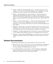
... Connector Pinouts (RJ-45) Function (HUB/NODE Switch in Function (HUB/NODE switch in Chapter 1, "Overview," lists the ports by model. Figure 1-3 in NODE Position or the Unmanaged Pin HUB Position) Hub on the position of the HUB/NODE switch. TX- 7 Unused Unused 8 Unused Unused A-2 Cisco 700 Series Router Installation Guide Ethernet Port Table A-2 compares the...
... Connector Pinouts (RJ-45) Function (HUB/NODE Switch in Function (HUB/NODE switch in Chapter 1, "Overview," lists the ports by model. Figure 1-3 in NODE Position or the Unmanaged Pin HUB Position) Hub on the position of the HUB/NODE switch. TX- 7 Unused Unused 8 Unused Unused A-2 Cisco 700 Series Router Installation Guide Ethernet Port Table A-2 compares the...

Installation Guide
Page 84
Figure A-1 Power Supply Comnnector 7 5 6 3 4 1 2 H6089 Common Port Assignments Table A-4 lists currently assigned TCP port numbers. A-4 Cisco 700 Series Router Installation Guide To the extent possible, UDP uses the same numbers. Common Port Assignments Power Connector Table A-4 shows the pinouts for the router power connector, and, Figure A-1 shows the location of the power connector pins. Table...
Figure A-1 Power Supply Comnnector 7 5 6 3 4 1 2 H6089 Common Port Assignments Table A-4 lists currently assigned TCP port numbers. A-4 Cisco 700 Series Router Installation Guide To the extent possible, UDP uses the same numbers. Common Port Assignments Power Connector Table A-4 shows the pinouts for the router power connector, and, Figure A-1 shows the location of the power connector pins. Table...
Installation Guide
Page 88
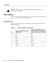
... connected. Click Start>Accessories>HyperTerminal. Select the COM port from the Connect using list to which the router is a data communications equipment (DCE) device. Enter a name in the Name field of the Connection Description ...• Data bits = 8 • Parity = None • Stop bits = 1 • Flow control = None B-2 Cisco 700 Series Router Installation Guide Establishing a Terminal Connection Figure B-1 Console Cable Connection (Cisco 766 Shown) H5063 CONFIG 10BASET NODE HUB Console cable Link ISDN S/T ISDN U S0 NT-1 +-350VV------10.5.2AA++/-/-52%5% Step 2 ...
... connected. Click Start>Accessories>HyperTerminal. Select the COM port from the Connect using list to which the router is a data communications equipment (DCE) device. Enter a name in the Name field of the Connection Description ...• Data bits = 8 • Parity = None • Stop bits = 1 • Flow control = None B-2 Cisco 700 Series Router Installation Guide Establishing a Terminal Connection Figure B-1 Console Cable Connection (Cisco 766 Shown) H5063 CONFIG 10BASET NODE HUB Console cable Link ISDN S/T ISDN U S0 NT-1 +-350VV------10.5.2AA++/-/-52%5% Step 2 ...

Installation Guide
Page 93
... software load process again. If the load was not successful, use Table B-3, which shows symptoms and possible solutions. Table B-4 lists the combination of blinking LEDs that indicate an error, along with the error code and a description of blinking LEDs indicates a ... problem. Table B-3 Software Download Command Troubleshooting Symptom Probable Cause and Solution Download takes significantly longer than the approximate time listed in the new software image file. Troubleshooting Software Downloads If the download was terminated prematurely, reset the interline and intercharacter...
... software load process again. If the load was not successful, use Table B-3, which shows symptoms and possible solutions. Table B-4 lists the combination of blinking LEDs that indicate an error, along with the error code and a description of blinking LEDs indicates a ... problem. Table B-3 Software Download Command Troubleshooting Symptom Probable Cause and Solution Download takes significantly longer than the approximate time listed in the new software image file. Troubleshooting Software Downloads If the download was terminated prematurely, reset the interline and intercharacter...

Installation Guide
Page 101
... C-2 lists the names and codes that simplifies the process of standardized features that might be referred to NI1. Provisioning the ISDN BRI Line C-5 Note The Cisco 765, Cisco 766, Cisco 775, and the Cisco 776 require two SPIDs for Cisco 765, Cisco 766, Cisco 775, and Cisco 776 routers. When... the analog telephone ports to the data and voice applications. Capability Package S Package S provides alternate voice and circuit-switched data with no additional features. The capability package ordering codes described in this section apply to by different names, depending...
... C-2 lists the names and codes that simplifies the process of standardized features that might be referred to NI1. Provisioning the ISDN BRI Line C-5 Note The Cisco 765, Cisco 766, Cisco 775, and the Cisco 776 require two SPIDs for Cisco 765, Cisco 766, Cisco 775, and Cisco 776 routers. When... the analog telephone ports to the data and voice applications. Capability Package S Package S provides alternate voice and circuit-switched data with no additional features. The capability package ordering codes described in this section apply to by different names, depending...

Installation Guide
Page 102
... access codes provided by the ISDN service ISDN line, photocopy the appropriate summary for the Cisco 765, Cisco 766, Cisco 775, and Cisco 776 routers. To access this service or to support voice priority on or off using the switch provisions listed in the following section contains provisioning summaries to use when you have any problems with...
... access codes provided by the ISDN service ISDN line, photocopy the appropriate summary for the Cisco 765, Cisco 766, Cisco 775, and Cisco 776 routers. To access this service or to support voice priority on or off using the switch provisions listed in the following section contains provisioning summaries to use when you have any problems with...

Installation Guide
Page 104
...switched data or voice/data4 D Signaling only MTERM 1 MAXB CHNL 2 ACT USR Y CSD 2 CSD CHL ANY TERMTYP TYPE A DISPLAY Y CA PREF 1 Call transfer Y 3-way call conferencing Y 1 Order this line provision when connecting the router... to the U interface. 2 A blank cell indicates that the configuration option is not available with Lucent 5ESS Custom switches. Note Incoming voice priority is... provision B2 for Lucent 5ESS Custom switches. C-8 Cisco 700 Series Router Installation Guide Table C-4 Lucent 5ESS Custom Provisioning Summary Line Provision ...
...switched data or voice/data4 D Signaling only MTERM 1 MAXB CHNL 2 ACT USR Y CSD 2 CSD CHL ANY TERMTYP TYPE A DISPLAY Y CA PREF 1 Call transfer Y 3-way call conferencing Y 1 Order this line provision when connecting the router... to the U interface. 2 A blank cell indicates that the configuration option is not available with Lucent 5ESS Custom switches. Note Incoming voice priority is... provision B2 for Lucent 5ESS Custom switches. C-8 Cisco 700 Series Router Installation Guide Table C-4 Lucent 5ESS Custom Provisioning Summary Line Provision ...

Installation Guide
Page 105
...conferencing Yes TEI DYNAMIC CS Yes EKTS No Set Option Key 1-ACOU 1, Key 2-AFC 1 Order this line provision when connecting the router to the U interface. 2 A blank cell indicates that the configuration option is not applicable to Functional Signaling Configuration -2 - - Table...line provision. Northern Telecom DMS-100 Custom Provisioning Summary Table C-5 lists the provisioning summary for Northern Telecom DMS-100 switches. Issue 2 (NI1) - Provisioning the ISDN BRI Line C-9 Use the provisioning summary listed in Table C-6 if your service provider does not support ACOU...
...conferencing Yes TEI DYNAMIC CS Yes EKTS No Set Option Key 1-ACOU 1, Key 2-AFC 1 Order this line provision when connecting the router to the U interface. 2 A blank cell indicates that the configuration option is not applicable to Functional Signaling Configuration -2 - - Table...line provision. Northern Telecom DMS-100 Custom Provisioning Summary Table C-5 lists the provisioning summary for Northern Telecom DMS-100 switches. Issue 2 (NI1) - Provisioning the ISDN BRI Line C-9 Use the provisioning summary listed in Table C-6 if your service provider does not support ACOU...

Installation Guide
Page 106
.... C-10 Cisco 700 Series Router Installation Guide TEI DYNAMIC CACH No CS Yes Call transfer Yes 3-way call conferencing Yes EKTS Yes Set Option 2 call appearances 1 If connecting at U interface. 2 A blank cell indicates that the configuration option is a list of configuration requirements for NI1 Table C-7 lists the router configuration requirements when using specific switch types. Router Configuration...
.... C-10 Cisco 700 Series Router Installation Guide TEI DYNAMIC CACH No CS Yes Call transfer Yes 3-way call conferencing Yes EKTS Yes Set Option 2 call appearances 1 If connecting at U interface. 2 A blank cell indicates that the configuration option is a list of configuration requirements for NI1 Table C-7 lists the router configuration requirements when using specific switch types. Router Configuration...

Installation Guide
Page 107
... number Optional set directory number 1 This parameter is not set with an Lucent 5ESS Custom switch. Table C-7 NI1 Configuration Parameter Router software Configuration U.S. Point-to-Point Configuration Table C-8 lists the router configuration requirements when using Cisco 700 series routers with a software command. 2 This parameter is not set when SPIDs are not used because it might cause...
... number Optional set directory number 1 This parameter is not set with an Lucent 5ESS Custom switch. Table C-7 NI1 Configuration Parameter Router software Configuration U.S. Point-to-Point Configuration Table C-8 lists the router configuration requirements when using Cisco 700 series routers with a software command. 2 This parameter is not set when SPIDs are not used because it might cause...