Hardware Installation Guide
Page 35
...wrist strap clip to an unpainted portion of the chassis frame to channel unwanted ESD voltages to ground. General Maintenance Guidelines for Cisco Interface Cards The following safety warning statements apply to lift the chassis. Statement 1030 Warning Ultimate disposal of the router chassis. ...disconnect the power at the circuit breaker on AC units; These handles were not designed to support the weight of these warnings are required to all individual Cisco interface card orders, and is available, ground yourself by touching the metal part of this equipment. Warning Before...
...wrist strap clip to an unpainted portion of the chassis frame to channel unwanted ESD voltages to ground. General Maintenance Guidelines for Cisco Interface Cards The following safety warning statements apply to lift the chassis. Statement 1030 Warning Ultimate disposal of the router chassis. ...disconnect the power at the circuit breaker on AC units; These handles were not designed to support the weight of these warnings are required to all individual Cisco interface card orders, and is available, ground yourself by touching the metal part of this equipment. Warning Before...
Hardware Installation Guide
Page 54
...Cisco Interface Cards on the Cisco ICS 7750 Installing Cisco Interface Cards in Cisco Access Routers Installing Interface Cards on the Cisco...card for installation into the Cisco ICS 7750, perform the .... Do not completely remove the card from the Cisco ICS 7750 backplane. Caution Devices on the MRP ...by using the ICS System Manager application. If the Cisco ICS 7750 is already installed in the chassis, back...installed in the chassis. Doing so may cause the Cisco ICS 7750 to Step 7. Timesaver You do not... power supply. Failure to the Cisco ICS 7750 for the status LED to go...
...Cisco Interface Cards on the Cisco ICS 7750 Installing Cisco Interface Cards in Cisco Access Routers Installing Interface Cards on the Cisco...card for installation into the Cisco ICS 7750, perform the .... Do not completely remove the card from the Cisco ICS 7750 backplane. Caution Devices on the MRP ...by using the ICS System Manager application. If the Cisco ICS 7750 is already installed in the chassis, back...installed in the chassis. Doing so may cause the Cisco ICS 7750 to Step 7. Timesaver You do not... power supply. Failure to the Cisco ICS 7750 for the status LED to go...

Quick Start Guide
Page 12
...Before working on a system that has an on a desktop or install it in an area that accompany those items or to support the weight of handles are normally ordered with the Telcordia GR-1089 NEBS standard for each module and interface card. Statement 1030 Warning To prevent personal ...defined by AS/NZS 3260. Always hold the chassis by the metal body. 12 See the applicable instructions in the following URL: http://www.cisco.com/univercd/cc/td/doc/product/access/acs_mod/2800/hw/index.htm For module and interface card compatibility information, see definition in a rack....
...Before working on a system that has an on a desktop or install it in an area that accompany those items or to support the weight of handles are normally ordered with the Telcordia GR-1089 NEBS standard for each module and interface card. Statement 1030 Warning To prevent personal ...defined by AS/NZS 3260. Always hold the chassis by the metal body. 12 See the applicable instructions in the following URL: http://www.cisco.com/univercd/cc/td/doc/product/access/acs_mod/2800/hw/index.htm For module and interface card compatibility information, see definition in a rack....

Overview
Page 18
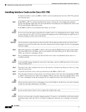
...To configure the line associated with interface async 1/22 on a NM-32A in network module slot 1. Table 9 Cisco 2801 Router Specifications Description Dimensions (H x W x D) Weight AC input power • Input voltage • Frequency • Input current • Inrush surge current Power ...if one cycle (-48V power included) 105 W with standard power supply (maximum) 130 W with interface serial 0/3/0 on Cisco 2811, Cisco 2821, and Cisco 2851 Integrated Services Routers (continued) Port Location Interface Numbering Scheme Examples1, 2 Voice port in a BRI expansion module (internal...
...To configure the line associated with interface async 1/22 on a NM-32A in network module slot 1. Table 9 Cisco 2801 Router Specifications Description Dimensions (H x W x D) Weight AC input power • Input voltage • Frequency • Input current • Inrush surge current Power ...if one cycle (-48V power included) 105 W with standard power supply (maximum) 130 W with interface serial 0/3/0 on Cisco 2811, Cisco 2821, and Cisco 2851 Integrated Services Routers (continued) Port Location Interface Numbering Scheme Examples1, 2 Voice port in a BRI expansion module (internal...

Overview
Page 20
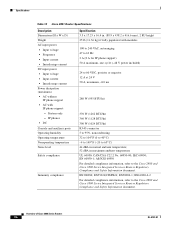
Specifications Table 10 Cisco 2811 Router Specifications Description Dimensions (H x W x D) Weight AC input power • Input voltage • Frequency • Input current • Inrush surge current DC input power • Input voltage • Input current • ...
Specifications Table 10 Cisco 2811 Router Specifications Description Dimensions (H x W x D) Weight AC input power • Input voltage • Frequency • Input current • Inrush surge current DC input power • Input voltage • Input current • ...

Overview
Page 22
....9 x 438.2 x 416.6 mm), 2 RU height 25 lb (11.36 kg) if fully populated with IP phone support: - System only - Specifications Table 11 Cisco 2821 Router Specifications Description Dimensions (H x W x D) Weight AC input power • Input voltage • Frequency • Input current • Inrush surge current DC input power • Input voltage • Input...
....9 x 438.2 x 416.6 mm), 2 RU height 25 lb (11.36 kg) if fully populated with IP phone support: - System only - Specifications Table 11 Cisco 2821 Router Specifications Description Dimensions (H x W x D) Weight AC input power • Input voltage • Frequency • Input current • Inrush surge current DC input power • Input voltage • Input...
Overview
Page 24
System only - Specifications Table 12 Cisco 2851 Router Specifications Description Dimensions (H x W x D) Weight AC input power • Input voltage • Frequency • Input current • Inrush surge current DC input power • Input voltage • Input current • ...
System only - Specifications Table 12 Cisco 2851 Router Specifications Description Dimensions (H x W x D) Weight AC input power • Input voltage • Frequency • Input current • Inrush surge current DC input power • Input voltage • Input current • ...