
Hardware Installation Guide
Page 2
... in this document or Website are the property of the following measures: • Turn the television or radio antenna until the interference stops. • Move the equipment to provide reasonable protection against harmful interference when the equipment ...pursuant to operate the product. All other trademarks mentioned in the United States and certain other company. (0502R) Cisco Aironet 1200 Series Access Point Hardware Installation Guide © 2005 Cisco Systems, Inc. The following information is , make certain the equipment and the television or radio are trademarks of...
... in this document or Website are the property of the following measures: • Turn the television or radio antenna until the interference stops. • Move the equipment to provide reasonable protection against harmful interference when the equipment ...pursuant to operate the product. All other trademarks mentioned in the United States and certain other company. (0502R) Cisco Aironet 1200 Series Access Point Hardware Installation Guide © 2005 Cisco Systems, Inc. The following information is , make certain the equipment and the television or radio are trademarks of...
Hardware Installation Guide
Page 4
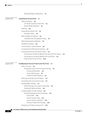
...2-4 Installation Summary 2-6 Connecting the 2.4-GHz Antennas 2-6 Connecting the 5-GHz External Antennas 2-7 Connecting the Ethernet and Power Cables 2-8 Connecting to an Ethernet Network with an Inline Power Source 2-9 Connecting to an Ethernet Network with Local Power 2-9 Powering Up the Access Point 2-10 3 C H A P T E R Configuring the Access Point for the First Time 3-1 Before You ... Types 3-11 Express Security Limitations 3-12 Using the Express Security Page 3-13 Assigning an IP Address Using the CLI 3-14 Cisco Aironet 1200 Series Access Point Hardware Installation Guide iv OL-4310-05
...2-4 Installation Summary 2-6 Connecting the 2.4-GHz Antennas 2-6 Connecting the 5-GHz External Antennas 2-7 Connecting the Ethernet and Power Cables 2-8 Connecting to an Ethernet Network with an Inline Power Source 2-9 Connecting to an Ethernet Network with Local Power 2-9 Powering Up the Access Point 2-10 3 C H A P T E R Configuring the Access Point for the First Time 3-1 Before You ... Types 3-11 Express Security Limitations 3-12 Using the Express Security Page 3-13 Assigning an IP Address Using the CLI 3-14 Cisco Aironet 1200 Series Access Point Hardware Installation Guide iv OL-4310-05
Hardware Installation Guide
Page 7
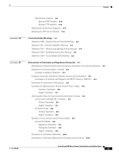
... B-7 Administrative Rules for Cisco Aironet Access Points in Taiwan B-7 Access Points with IEEE 802.11a Radios B-7 Chinese Translation B-7 English Translation B-7 All Access Points B-8 Chinese Translation B-8 English Translation B-8 Operation of Cisco Aironet Access Points in Brazil B-9 Access Point Model B-9 Regulatory Information B-9 Portuguese Translation B-9 English Translation B-9 Declaration of Conformity Statements B-10 Declaration of Conformity Statements for European Union Countries B-10 OL-4310-05 Cisco Aironet 1200 Series Access Point Hardware Installation Guide...
... B-7 Administrative Rules for Cisco Aironet Access Points in Taiwan B-7 Access Points with IEEE 802.11a Radios B-7 Chinese Translation B-7 English Translation B-7 All Access Points B-8 Chinese Translation B-8 English Translation B-8 Operation of Cisco Aironet Access Points in Brazil B-9 Access Point Model B-9 Regulatory Information B-9 Portuguese Translation B-9 English Translation B-9 Declaration of Conformity Statements B-10 Declaration of Conformity Statements for European Union Countries B-10 OL-4310-05 Cisco Aironet 1200 Series Access Point Hardware Installation Guide...
Hardware Installation Guide
Page 10
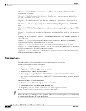
...information for the access point. Appendix B, "Declarations of Conformity and Regulatory Information," provides declarations of the safety warnings that connects to the access point's serial console port. Appendix D, "Channels and Antenna Settings," lists the access point radio channels and ... Instructions," describes how to mount the access point on a desktop, wall, or ceiling. Cisco Aironet 1200 Series Access Point Hardware Installation Guide x OL-4310-05 Interactive examples use the web-browser interface to configure the access point. Notes, cautions, and timesavers use ...
...information for the access point. Appendix B, "Declarations of Conformity and Regulatory Information," provides declarations of the safety warnings that connects to the access point's serial console port. Appendix D, "Channels and Antenna Settings," lists the access point radio channels and ... Instructions," describes how to mount the access point on a desktop, wall, or ceiling. Cisco Aironet 1200 Series Access Point Hardware Installation Guide x OL-4310-05 Interactive examples use the web-browser interface to configure the access point. Notes, cautions, and timesavers use ...
Hardware Installation Guide
Page 20
... radio modules contain dual integrated omnidirectional antennas and directional antennas for the RM21A or RM22A radio module, least congested, often results in the UNII 5-GHz frequency bands. You can also upgrade an access point configured for single-radio operation to ... describes access point features. Refer to Appendix C, "Access Point Specifications," for single- Key hardware features of these frequencies that the CB20A client radio does not support: channel 149 (5745 GHz), channel 153 (5765 GHz), channel 157 (5785 GHz), and channel 161 Cisco Aironet 1200 Series Access Point Hardware...
... radio modules contain dual integrated omnidirectional antennas and directional antennas for the RM21A or RM22A radio module, least congested, often results in the UNII 5-GHz frequency bands. You can also upgrade an access point configured for single-radio operation to ... describes access point features. Refer to Appendix C, "Access Point Specifications," for single- Key hardware features of these frequencies that the CB20A client radio does not support: channel 149 (5745 GHz), channel 153 (5765 GHz), channel 157 (5785 GHz), and channel 161 Cisco Aironet 1200 Series Access Point Hardware...
Hardware Installation Guide
Page 27
CH A P T E R 2 Installing the Access Point This chapter describes the setup of the access point and includes the following sections: • Safety Information, page 2-2 • Warnings, page 2-2 • Unpacking the Access Point, page 2-3 • Basic Installation Guidelines, page 2-3 • Before Beginning the Installation, page 2-4 • Installation Summary, page 2-6 • Connecting the 2.4-GHz Antennas, page 2-6 • Connecting the Ethernet and Power Cables, page 2-8 OL-4310-05 Cisco Aironet 1200 Series Access Point Hardware Installation Guide 2-1
CH A P T E R 2 Installing the Access Point This chapter describes the setup of the access point and includes the following sections: • Safety Information, page 2-2 • Warnings, page 2-2 • Unpacking the Access Point, page 2-3 • Basic Installation Guidelines, page 2-3 • Before Beginning the Installation, page 2-4 • Installation Summary, page 2-6 • Connecting the 2.4-GHz Antennas, page 2-6 • Connecting the Ethernet and Power Cables, page 2-8 OL-4310-05 Cisco Aironet 1200 Series Access Point Hardware Installation Guide 2-1
Hardware Installation Guide
Page 28
... the constraints posed by FCC certified equipment. Statement 245B Warning In order to comply with approved Cisco Aironet antennas, Cisco Aironet products meet the uncontrolled environmental limits found in this manual will result in Appendix A, "Translated Safety Warnings." Statement 1001 Cisco Aironet 1200 Series Access Point Hardware Installation Guide 2-2 OL-4310-05 Warning Read the installation instructions before you connect the...
... the constraints posed by FCC certified equipment. Statement 245B Warning In order to comply with approved Cisco Aironet antennas, Cisco Aironet products meet the uncontrolled environmental limits found in this manual will result in Appendix A, "Translated Safety Warnings." Statement 1001 Cisco Aironet 1200 Series Access Point Hardware Installation Guide 2-2 OL-4310-05 Warning Read the installation instructions before you connect the...
Hardware Installation Guide
Page 30
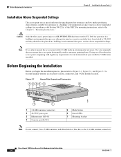
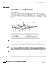
... (RJ-45) 5 Mode button 6 Status LEDs 7 Mounting bracket Note Do not connect Cisco 5-GHz antennas with blue labels or blue dots to UL 2043 and they should not be placed in a building's environmental air space, such as above suspended ceilings. Cisco Aironet 1200 Series Access Point Hardware Installation Guide 2-4 OL-4310-05 no other power injectors or power modules...
... (RJ-45) 5 Mode button 6 Status LEDs 7 Mounting bracket Note Do not connect Cisco 5-GHz antennas with blue labels or blue dots to UL 2043 and they should not be placed in a building's environmental air space, such as above suspended ceilings. Cisco Aironet 1200 Series Access Point Hardware Installation Guide 2-4 OL-4310-05 no other power injectors or power modules...

Hardware Installation Guide
Page 31
... radio module) 3 Access point Figure 2-3 RM22A Radio Module with External RP-TNC Antenna Connectors ] 1 Left 5-GHz antenna connector (RP-TNC) 4 Right 5-GHz antenna connector (RP-TNC) 2 Blue 5-GHz label 5 5-GHz radio 3 Module mounting screws Note Only connect Cisco 5-GHz antennas with blue labels or blue dots to the RM22A radio module. OL-4310-05 Cisco Aironet 1200 Series Access Point Hardware Installation Guide...
... radio module) 3 Access point Figure 2-3 RM22A Radio Module with External RP-TNC Antenna Connectors ] 1 Left 5-GHz antenna connector (RP-TNC) 4 Right 5-GHz antenna connector (RP-TNC) 2 Blue 5-GHz label 5 5-GHz radio 3 Module mounting screws Note Only connect Cisco 5-GHz antennas with blue labels or blue dots to the RM22A radio module. OL-4310-05 Cisco Aironet 1200 Series Access Point Hardware Installation Guide...

Hardware Installation Guide
Page 32
..., wall, or ceiling. Cisco Aironet 1200 Series Access Point Hardware Installation Guide 2-6 OL-4310-05 If you are used for the 2.4-GHz radio. Connecting the 2.4-GHz Antennas The access point supports a single antenna or dual diversity antennas. Note RP-TNC antenna connectors are using two antennas for connector locations). Installation Summary Chapter 2 Installing the Access Point Installation Summary While installing the access point, you must perform the...
..., wall, or ceiling. Cisco Aironet 1200 Series Access Point Hardware Installation Guide 2-6 OL-4310-05 If you are used for the 2.4-GHz radio. Connecting the 2.4-GHz Antennas The access point supports a single antenna or dual diversity antennas. Note RP-TNC antenna connectors are using two antennas for connector locations). Installation Summary Chapter 2 Installing the Access Point Installation Summary While installing the access point, you must perform the...

Hardware Installation Guide
Page 33
... Access Point Connecting the 5-GHz External Antennas Connecting the 5-GHz External Antennas The access point supports an RM22A radio module for diversity coverage, attach the second antenna cable to the Left 5-GHz (RP-TNC) antenna connector. If you are using two antennas for use with your Cisco Aironet antenna, refer to Figure 2-3 for connector locations). Step 2 To mount your antenna. OL-4310-05 Cisco Aironet 1200 Series Access Point...
... Access Point Connecting the 5-GHz External Antennas Connecting the 5-GHz External Antennas The access point supports an RM22A radio module for diversity coverage, attach the second antenna cable to the Left 5-GHz (RP-TNC) antenna connector. If you are using two antennas for use with your Cisco Aironet antenna, refer to Figure 2-3 for connector locations). Step 2 To mount your antenna. OL-4310-05 Cisco Aironet 1200 Series Access Point...
Hardware Installation Guide
Page 68
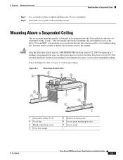
... hasp Note The Cisco Aironet 1200 Series Access Point provides adequate fire resistance and low smoke-producing characteristics suitable for your installation. Doing so will upgrade to mark the positions of the mounting holes for operation in a building's environmental air space (such as a template to a 5-GHz radio, Cisco recommends that you mount the access point horizontally with its antennas pointing down. Note...
... hasp Note The Cisco Aironet 1200 Series Access Point provides adequate fire resistance and low smoke-producing characteristics suitable for your installation. Doing so will upgrade to mark the positions of the mounting holes for operation in a building's environmental air space (such as a template to a 5-GHz radio, Cisco recommends that you mount the access point horizontally with its antennas pointing down. Note...
Hardware Installation Guide
Page 71
...Cisco Aironet 1200 Series Access Point Hardware Installation Guide 6-5 Step 8 Attach the access point to be integrated into the T-bar grid above the top surface of a suspended ceiling. no other power injectors or power modules have been tested to UL 2043 and they should not be helpful to refer to allow room for operation in a building's environmental air... space, such as the Erico 512A and BHC, you orient the access point antenna just above the tiles of a standard ceiling tile. Caution Only the ...
...Cisco Aironet 1200 Series Access Point Hardware Installation Guide 6-5 Step 8 Attach the access point to be integrated into the T-bar grid above the top surface of a suspended ceiling. no other power injectors or power modules have been tested to UL 2043 and they should not be helpful to refer to allow room for operation in a building's environmental air... space, such as the Erico 512A and BHC, you orient the access point antenna just above the tiles of a standard ceiling tile. Caution Only the ...

Hardware Installation Guide
Page 72
...antenna for patch or omnidirectional operation as desired. Cisco Aironet 1200 Series Access Point Hardware Installation Guide 6-6 OL-4310-05 Figure 6-5 Access Point Mounting Bracket 95739 Note The illustration shows the access point mounting bracket mounted perpendicular to mount the access point above a suspended ceiling. Step 3 Step 4 Determine the location in the ceiling where you will mount the access point... the T-bar hanger). Orient the access point 2-GHz antennas so that they are pointing down when mounted on the access point mounting bracket. Figure 6-4 Mounting Bracket...
...antenna for patch or omnidirectional operation as desired. Cisco Aironet 1200 Series Access Point Hardware Installation Guide 6-6 OL-4310-05 Figure 6-5 Access Point Mounting Bracket 95739 Note The illustration shows the access point mounting bracket mounted perpendicular to mount the access point above a suspended ceiling. Step 3 Step 4 Determine the location in the ceiling where you will mount the access point... the T-bar hanger). Orient the access point 2-GHz antennas so that they are pointing down when mounted on the access point mounting bracket. Figure 6-4 Mounting Bracket...

Hardware Installation Guide
Page 73
...Access Point to the Mounting Bracket Follow these steps to attach the access point to the mounting bracket: Step 1 Step 2 Step 3 Step 4 Step 5 Step 6 Line up the three mounting pins on the access point with the U.S. OL-4310-05 Cisco Aironet 1200 Series Access Point... Insert the access point into the access point's 48-VDC power port. Attach and adjust the antenna(s) or antenna cables. Attach the access point to the access point mounting bracket (refer to the "Attaching the Access Point to the access point. Chapter 6 Mounting Instructions Attaching the Access Point to the ...
...Access Point to the Mounting Bracket Follow these steps to attach the access point to the mounting bracket: Step 1 Step 2 Step 3 Step 4 Step 5 Step 6 Line up the three mounting pins on the access point with the U.S. OL-4310-05 Cisco Aironet 1200 Series Access Point... Insert the access point into the access point's 48-VDC power port. Attach and adjust the antenna(s) or antenna cables. Attach the access point to the access point mounting bracket (refer to the "Attaching the Access Point to the access point. Chapter 6 Mounting Instructions Attaching the Access Point to the ...

Hardware Installation Guide
Page 78
...: Step 1 Push the card-retaining clips (on Blank Spacer Card 2 31 74248 1 Card-retaining clips 2 Antenna connector (white wire) 3 Antenna connector (black wire) Step 2 Carefully bend the card near the slots in the internal mini-PCI connector. Cisco Aironet 1200 Series Access Point Hardware Installation Guide 7-4 OL-4310-05 Caution Handle all components carefully and observe all ESD...
...: Step 1 Push the card-retaining clips (on Blank Spacer Card 2 31 74248 1 Card-retaining clips 2 Antenna connector (white wire) 3 Antenna connector (black wire) Step 2 Carefully bend the card near the slots in the internal mini-PCI connector. Cisco Aironet 1200 Series Access Point Hardware Installation Guide 7-4 OL-4310-05 Caution Handle all components carefully and observe all ESD...

Hardware Installation Guide
Page 79
...improper handling. Caution To avoid damaging the antenna wire assemblies, handle them by ESD from your fingers to the "Installing a 2.4-GHz Radio" section. Step 1 Use your access point, follow these steps: Caution The internal access point components and the 2.4-GHz radio can ... handle them by using a pair of long-nose pliers during the removal process. Caution The antenna connectors can be damaged by their connectors. OL-4310-05 Cisco Aironet 1200 Series Access Point Hardware Installation Guide 7-5 Step 4 Remove the blank spacer card from the blank spacer card. ...
...improper handling. Caution To avoid damaging the antenna wire assemblies, handle them by ESD from your fingers to the "Installing a 2.4-GHz Radio" section. Step 1 Use your access point, follow these steps: Caution The internal access point components and the 2.4-GHz radio can ... handle them by using a pair of long-nose pliers during the removal process. Caution The antenna connectors can be damaged by their connectors. OL-4310-05 Cisco Aironet 1200 Series Access Point Hardware Installation Guide 7-5 Step 4 Remove the blank spacer card from the blank spacer card. ...

Hardware Installation Guide
Page 81
... wire) 3 Mini-PCI connector Step 4 Connect the white antenna wire connector to touch components on the board or the gold connector pins. Grasp the radio card only on the edges, being careful not to the radio card antenna connector marked by the black label (see Figure 7-4). OL-4310-05 Cisco Aironet 1200 Series Access Point Hardware Installation Guide 7-7
... wire) 3 Mini-PCI connector Step 4 Connect the white antenna wire connector to touch components on the board or the gold connector pins. Grasp the radio card only on the edges, being careful not to the radio card antenna connector marked by the black label (see Figure 7-4). OL-4310-05 Cisco Aironet 1200 Series Access Point Hardware Installation Guide 7-7
Hardware Installation Guide
Page 82
... 7 b. If they are touching, carefully rotate them in opposite directions until it clicks into the access point's mini-PCI connector by following these steps: a. Cisco Aironet 1200 Series Access Point Hardware Installation Guide 7-8 OL-4310-05 Depending on your access point. Caution Do not allow antenna connectors to touch while power is applied, or the radio can be up to three...
... 7 b. If they are touching, carefully rotate them in opposite directions until it clicks into the access point's mini-PCI connector by following these steps: a. Cisco Aironet 1200 Series Access Point Hardware Installation Guide 7-8 OL-4310-05 Depending on your access point. Caution Do not allow antenna connectors to touch while power is applied, or the radio can be up to three...

Hardware Installation Guide
Page 87
... Upgrade Removing a 5-GHz Radio Module Step 3 Remove the 5-GHz access cover using the supplied Torx L-wrench (Figure 8-2). Figure 8-2 5-GHz Radio Module 1 1 2 3 74631 1 Mounting screws 2 5-GHz radio module antenna 3 Access point Note Do not attempt to remove the mounting screws from the access point. OL-4310-05 Cisco Aironet 1200 Series Access Point Hardware Installation Guide 8-3 Unscrew the two mounting screws using the...
... Upgrade Removing a 5-GHz Radio Module Step 3 Remove the 5-GHz access cover using the supplied Torx L-wrench (Figure 8-2). Figure 8-2 5-GHz Radio Module 1 1 2 3 74631 1 Mounting screws 2 5-GHz radio module antenna 3 Access point Note Do not attempt to remove the mounting screws from the access point. OL-4310-05 Cisco Aironet 1200 Series Access Point Hardware Installation Guide 8-3 Unscrew the two mounting screws using the...


