
Hardware Installation Guide
Page 5
... SSID and Radio Behavior 5-4 Enabling the Radio Interfaces 5-5 SSID 5-5 WEP Keys 5-5 Security Settings 5-5 Running the Carrier Busy Test 5-6 Running the Ping or Link Test 5-7 Resetting to the Default Configuration 5-7 Using the MODE Button 5-8 Using the Web Browser Interface 5-8 Reloading the Access Point Image 5-9 Using the MODE button 5-9 Web Browser Interface... Access Point to Autonomous Mode 6-5 MODE Button Setting 6-6 Obtaining the Autonomous Access Point Image File 6-6 Obtaining the TFTP Server Software 6-7 OL-4309-07 Cisco Aironet 1100 Series Access Point Hardware Installation Guide v
... SSID and Radio Behavior 5-4 Enabling the Radio Interfaces 5-5 SSID 5-5 WEP Keys 5-5 Security Settings 5-5 Running the Carrier Busy Test 5-6 Running the Ping or Link Test 5-7 Resetting to the Default Configuration 5-7 Using the MODE Button 5-8 Using the Web Browser Interface 5-8 Reloading the Access Point Image 5-9 Using the MODE button 5-9 Web Browser Interface... Access Point to Autonomous Mode 6-5 MODE Button Setting 6-6 Obtaining the Autonomous Access Point Image File 6-6 Obtaining the TFTP Server Software 6-7 OL-4309-07 Cisco Aironet 1100 Series Access Point Hardware Installation Guide v

Hardware Installation Guide
Page 59
..., page 5-6 • Running the Ping or Link Test, page 5-7 • Resetting to the Default Configuration, page 5-7 • Reloading the Access Point Image, page 5-9 • Obtaining the Access Point Image File, page 5-11 • Obtaining the TFTP Server Software, page 5-11 OL-4309-07 Cisco Aironet 1100 Series Access Point Hardware Installation Guide 5-1
..., page 5-6 • Running the Ping or Link Test, page 5-7 • Resetting to the Default Configuration, page 5-7 • Reloading the Access Point Image, page 5-9 • Obtaining the Access Point Image File, page 5-11 • Obtaining the TFTP Server Software, page 5-11 OL-4309-07 Cisco Aironet 1100 Series Access Point Hardware Installation Guide 5-1

Hardware Installation Guide
Page 61
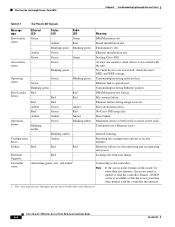
... Red Blinking green - At least one wireless client device is operational. Transmitting/receiving radio packets. Ethernet failure during image recovery. Red Firmware failure; Reset Failure Red Status LED - Starting Cisco IOS. Ethernet link is associated with the unit. Red Red - Boot failure. try disconnecting and reconnecting unit power. - Chapter 5 Troubleshooting Autonomous Access...
... Red Blinking green - At least one wireless client device is operational. Transmitting/receiving radio packets. Ethernet failure during image recovery. Red Firmware failure; Reset Failure Red Status LED - Starting Cisco IOS. Ethernet link is associated with the unit. Red Red - Boot failure. try disconnecting and reconnecting unit power. - Chapter 5 Troubleshooting Autonomous Access...
Hardware Installation Guide
Page 65
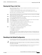
... Click Start. b. When the test stops, the test results are case sensitive. Resetting to completely reset the configuration. Press Enter. The default username is Cisco and the default password is Cisco. Click the MAC address of an associated access point, and the Statistics page for ...For additional information on access point default behavior, refer to evaluate the communication link with the wireless link. OL-4309-07 Cisco Aironet 1100 Series Access Point Hardware Installation Guide 5-7 Chapter 5 Troubleshooting Autonomous Access Points Running the Ping or Link Test Running ...
... Click Start. b. When the test stops, the test results are case sensitive. Resetting to completely reset the configuration. Press Enter. The default username is Cisco and the default password is Cisco. Click the MAC address of an associated access point, and the Statistics page for ...For additional information on access point default behavior, refer to evaluate the communication link with the wireless link. OL-4309-07 Cisco Aironet 1100 Series Access Point Hardware Installation Guide 5-7 Chapter 5 Troubleshooting Autonomous Access Points Running the Ping or Link Test Running ...
Hardware Installation Guide
Page 66
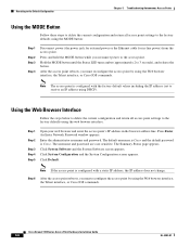
Resetting to the Default Configuration Chapter 5 Troubleshooting Autonomous Access Points ... reboots, you must reconfigure the access point by using the Web browser interface, the Telnet interface, or Cisco IOS commands. Cisco Aironet 1100 Series Access Point Hardware Installation Guide 5-8 OL-4309-07 Press Enter. Press and hold the ...MODE button while you must reconfigure the access point by using the Web browser interface, the Telnet interface, or Cisco IOS commands. After the access point reboots, you reconnect power to receive an IP address using the MODE button:...
Resetting to the Default Configuration Chapter 5 Troubleshooting Autonomous Access Points ... reboots, you must reconfigure the access point by using the Web browser interface, the Telnet interface, or Cisco IOS commands. Cisco Aironet 1100 Series Access Point Hardware Installation Guide 5-8 OL-4309-07 Press Enter. Press and hold the ...MODE button while you must reconfigure the access point by using the Web browser interface, the Telnet interface, or Cisco IOS commands. After the access point reboots, you reconnect power to receive an IP address using the MODE button:...
Hardware Installation Guide
Page 67
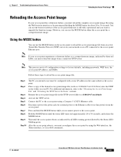
... Access Points Reloading the Access Point Image Reloading the Access Point Image If your PC. Note This process resets all LEDs turning green followed by using the Web interface, the Telnet interface, or Cisco IOS commands. Place a copy of the desired access point image file (such as the access point. OL-4309...
... Access Points Reloading the Access Point Image Reloading the Access Point Image If your PC. Note This process resets all LEDs turning green followed by using the Web interface, the Telnet interface, or Cisco IOS commands. Place a copy of the desired access point image file (such as the access point. OL-4309...
Hardware Installation Guide
Page 74
...receiving Ethernet packets. Red Red - Red Green Red No Cisco IOS image file. Association - Green Green - Boot Loader Red - Amber Green Amber Boot environment error. Blinking amber Green - Resetting the configuration options to the controller. try disconnecting and reconnecting...the highest priority and overrides other status indications. Blinking green - No client devices are associated; Green Green Green Starting Cisco IOS. Ethernet link is unable to find the controller. Blinking amber - Alternating green, red , and amber1 Loading ...
...receiving Ethernet packets. Red Red - Red Green Red No Cisco IOS image file. Association - Green Green - Boot Loader Red - Amber Green Amber Boot environment error. Blinking amber Green - Resetting the configuration options to the controller. try disconnecting and reconnecting...the highest priority and overrides other status indications. Blinking green - No client devices are associated; Green Green Green Starting Cisco IOS. Ethernet link is unable to find the controller. Blinking amber - Alternating green, red , and amber1 Loading ...

Hardware Installation Guide
Page 115
...5-4 bridge configuration 1-1 C compliance C-3 configuring DHCP Option 43 F-2 connectors C-1, C-3 controller discovery process 2-5 D data rates C-2 declarations of conformity B-1 default configuration, resetting to defaults 5-7 deployment access points 2-5 process 2-5 DHCP Option 43 6-2, F-1 DHCP pool F-2 discovery process DHCP server 2-5 DNS server 2-5 locally stored 2-5 OL-...C-1 installation guidelines 2-3 K key features 1-3 L LED indicators, radio traffic 5-2, 6-3 M MAC information 2-5 Mode button 5-9 modulation C-2 Cisco Aironet 1100 Series Access Point Hardware Installation Guide IN-1
...5-4 bridge configuration 1-1 C compliance C-3 configuring DHCP Option 43 F-2 connectors C-1, C-3 controller discovery process 2-5 D data rates C-2 declarations of conformity B-1 default configuration, resetting to defaults 5-7 deployment access points 2-5 process 2-5 DHCP Option 43 6-2, F-1 DHCP pool F-2 discovery process DHCP server 2-5 DNS server 2-5 locally stored 2-5 OL-...C-1 installation guidelines 2-3 K key features 1-3 L LED indicators, radio traffic 5-2, 6-3 M MAC information 2-5 Mode button 5-9 modulation C-2 Cisco Aironet 1100 Series Access Point Hardware Installation Guide IN-1
Hardware Installation Guide
Page 116
... server 5-9 type-length-value (TLV) F-2 P package contents 2-3 password reset 5-7 power connecting 2-7 injector 2-7 input C-1 output C-2 priming access points E-1 process, controller discovery 2-5 R radio indicator 5-2, 6-3 specifications C-2 range C-3 regulatory information B-1, C-3 reloading access point image 5-9 RF exposure B-6 U unpacking 2-3 V vendor class identifier (VCI) F-2 voltage range C-1 W warnings 2-2, A-1 web site, Cisco Software Center 5-11, 6-6 weight, access point C-1 WEP key 5-5 S safety...
... server 5-9 type-length-value (TLV) F-2 P package contents 2-3 password reset 5-7 power connecting 2-7 injector 2-7 input C-1 output C-2 priming access points E-1 process, controller discovery 2-5 R radio indicator 5-2, 6-3 specifications C-2 range C-3 regulatory information B-1, C-3 reloading access point image 5-9 RF exposure B-6 U unpacking 2-3 V vendor class identifier (VCI) F-2 voltage range C-1 W warnings 2-2, A-1 web site, Cisco Software Center 5-11, 6-6 weight, access point C-1 WEP key 5-5 S safety...


