Hardware Installation Guide
Page 8
... the lightweight access point. Chapter 6, "Troubleshooting Lightweight Access Points," provides troubleshooting procedures for which you supply values are in italic. • Square brackets ([ ]) mean optional elements. • Braces ...points with the autonomous access point. Appendix D, "Channels and Maximum Power Levels," indicates how to configure DHCP Option 43 for basic problems ..."Troubleshooting Autonomous Access Points," provides troubleshooting procedures for lightweight access points. Cisco Aironet 1100 Series Access Point Hardware Installation Guide viii OL-4309-07 ...
... the lightweight access point. Chapter 6, "Troubleshooting Lightweight Access Points," provides troubleshooting procedures for which you supply values are in italic. • Square brackets ([ ]) mean optional elements. • Braces ...points with the autonomous access point. Appendix D, "Channels and Maximum Power Levels," indicates how to configure DHCP Option 43 for basic problems ..."Troubleshooting Autonomous Access Points," provides troubleshooting procedures for lightweight access points. Cisco Aironet 1100 Series Access Point Hardware Installation Guide viii OL-4309-07 ...
Hardware Installation Guide
Page 20
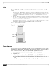
...power sources: • Power supply (input 100-240 VAC, 50-60 Hz, output 48 VDC, 0.2A minimum) • Inline power from an external power module or through inline power using the Ethernet cable. Hardware Features Chapter 1 Overview LEDs The three LEDs on the top of providing inline power, such as the Cisco Catalyst Inline Power Patch Panel Cisco...but is not associated with at least one wireless client. Cisco Aironet Power Injector (Cisco AIR-PWRINJ3= or Cisco AIR-PWRINJ-FIB= ) - An inline power patch panel, such as the Cisco Catalyst 3500XL, 3550, 4000, or 6500 - Blinking ...
...power sources: • Power supply (input 100-240 VAC, 50-60 Hz, output 48 VDC, 0.2A minimum) • Inline power from an external power module or through inline power using the Ethernet cable. Hardware Features Chapter 1 Overview LEDs The three LEDs on the top of providing inline power, such as the Cisco Catalyst Inline Power Patch Panel Cisco...but is not associated with at least one wireless client. Cisco Aironet Power Injector (Cisco AIR-PWRINJ3= or Cisco AIR-PWRINJ-FIB= ) - An inline power patch panel, such as the Cisco Catalyst 3500XL, 3550, 4000, or 6500 - Blinking ...
Hardware Installation Guide
Page 33
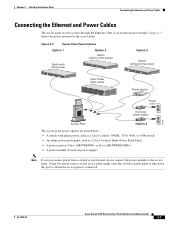
... AP/ BRITDOGE NETWOTROK Power cord Universal power supply Access Point Option 4 The access point power options are listed below: • A switch with inline power, such as a Cisco Catalyst 3500XL, 3550, 4000, or 6500 switch • An inline power patch panel, such as a Cisco Catalyst Inline Power Patch Panel • A power injector (Cisco AIR-PWRINJ3= or Cisco AIR-PWRINJ-FIB= ) • A power module (Universal power supply) 81173 81596...
... AP/ BRITDOGE NETWOTROK Power cord Universal power supply Access Point Option 4 The access point power options are listed below: • A switch with inline power, such as a Cisco Catalyst 3500XL, 3550, 4000, or 6500 switch • An inline power patch panel, such as a Cisco Catalyst Inline Power Patch Panel • A power injector (Cisco AIR-PWRINJ3= or Cisco AIR-PWRINJ-FIB= ) • A power module (Universal power supply) 81173 81596...
Hardware Installation Guide
Page 34
... the Cisco Aironet Power Injector specified for the access point. Using the power injector with other end of the Ethernet cable into an approved 100- no other end labeled To Network to UL 2043 and they should not be placed in a building's environmental air space; to power the access point, you must use the power supply included...
... the Cisco Aironet Power Injector specified for the access point. Using the power injector with other end of the Ethernet cable into an approved 100- no other end labeled To Network to UL 2043 and they should not be placed in a building's environmental air space; to power the access point, you must use the power supply included...

Hardware Installation Guide
Page 43
... to make it with the U.S. Attach the access point to supply power. Therefore, you must use the Ethernet cable to the access point mounting bracket. Note The power module and power injector are securely attached to the T-rails. Step 1 Step ...power jack. Verify that the access point is required in the bracket mounting clip. National Electrical Safety Code. Connect the Ethernet cables to a building structural element and the hole provided in order to comply with a padlock (Master Lock model 120T, 121T or equivalent). Figure 3-6 Security Hasp Adapter 81177 OL-4309-07 Cisco...
... to make it with the U.S. Attach the access point to supply power. Therefore, you must use the Ethernet cable to the access point mounting bracket. Note The power module and power injector are securely attached to the T-rails. Step 1 Step ...power jack. Verify that the access point is required in the bracket mounting clip. National Electrical Safety Code. Connect the Ethernet cables to a building structural element and the hole provided in order to comply with a padlock (Master Lock model 120T, 121T or equivalent). Figure 3-6 Security Hasp Adapter 81177 OL-4309-07 Cisco...

Hardware Installation Guide
Page 45
...place the holster. Step 1 Step 2 Step 3 Select a suitable location to mount the access point on a desktop or other horizontal surface using the supplied desktop holster. Chapter 3 Mounting Instructions Using the Desktop Holster Step 6 Position the mounting bracket over the partition wall and adjust it to secure the ...access point with a Kensington lock, attach it now. Connect the Ethernet and power cables. • If you . See Figure 3-8. Position the holster so that its back side is facing you are going to fit. OL-...
...place the holster. Step 1 Step 2 Step 3 Select a suitable location to mount the access point on a desktop or other horizontal surface using the supplied desktop holster. Chapter 3 Mounting Instructions Using the Desktop Holster Step 6 Position the mounting bracket over the partition wall and adjust it to secure the ...access point with a Kensington lock, attach it now. Connect the Ethernet and power cables. • If you . See Figure 3-8. Position the holster so that its back side is facing you are going to fit. OL-...


