Hardware Installation Guide
Page 6
... GLOSSARY INDEX Installing Your Router 2-5 Connecting Ethernet Devices 2-6 Connecting an ISDN Line 2-10 Connecting an IDSL Line 2-13 Connecting a Digital Telephone 2-14 Connecting an Analog Telephone, Fax, or Modem 2-15 Connecting a Terminal or PC 2-17 Connecting the Power Supply 2-18 Mounting Your Router 2-18 Mounting on a Table 2-18 Mounting on...Contacting Your Cisco Reseller 3-7 ISDN and IDSL Concepts A-1 Specifications and Cables B-1 System Specifications B-1 Port Connector Pinouts B-2 Cabling Specifications B-6 Ethernet Cable Specifications B-7 Maximum Cable Distances B-7 Cisco 800 Series...
... GLOSSARY INDEX Installing Your Router 2-5 Connecting Ethernet Devices 2-6 Connecting an ISDN Line 2-10 Connecting an IDSL Line 2-13 Connecting a Digital Telephone 2-14 Connecting an Analog Telephone, Fax, or Modem 2-15 Connecting a Terminal or PC 2-17 Connecting the Power Supply 2-18 Mounting Your Router 2-18 Mounting on a Table 2-18 Mounting on...Contacting Your Cisco Reseller 3-7 ISDN and IDSL Concepts A-1 Specifications and Cables B-1 System Specifications B-1 Port Connector Pinouts B-2 Cabling Specifications B-6 Ethernet Cable Specifications B-7 Maximum Cable Distances B-7 Cisco 800 Series...
Hardware Installation Guide
Page 16
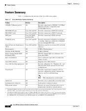
... command-line interface and for the DRAM upgrade kits are connected to telephone services through ISDN line. Locking power connector All Locks power connector in a different color from other LEDs. Wall-mount feature All Brackets on the Cisco 802 and Cisco 804 routers ...10 Mbps) Ethernet networks. Provides connection to Cisco 802 and Cisco 804 routers. 2. Color-coded ports and cables to reduce the chance of installation Cisco IOS software Cisco 800 Fast Step application Console port Routers All Cisco 801 and 803 Cisco 802 and 804 Cisco 802 IDSL and 804 IDSL Cisco 803 and 804 Cisco...
... command-line interface and for the DRAM upgrade kits are connected to telephone services through ISDN line. Locking power connector All Locks power connector in a different color from other LEDs. Wall-mount feature All Brackets on the Cisco 802 and Cisco 804 routers ...10 Mbps) Ethernet networks. Provides connection to Cisco 802 and Cisco 804 routers. 2. Color-coded ports and cables to reduce the chance of installation Cisco IOS software Cisco 800 Fast Step application Console port Routers All Cisco 801 and 803 Cisco 802 and 804 Cisco 802 IDSL and 804 IDSL Cisco 803 and 804 Cisco...

Hardware Installation Guide
Page 18
...cause severe injury or damage your router. ISDN BRI S/T port Connect to physically secure router. Power switch l = On. = Standby or no power output. 11666 LINK HUB NO HUB ETHERNET 10 BASE T Cisco 801 CONSOLE ISDN S/T Cable lock Use cable lock to external NT1 or ISDN wall jack. ...On when connected. device connection. Figure 1-4 Cisco 801 Router Back Panel Link LED Indicates state of suitability ...
...cause severe injury or damage your router. ISDN BRI S/T port Connect to physically secure router. Power switch l = On. = Standby or no power output. 11666 LINK HUB NO HUB ETHERNET 10 BASE T Cisco 801 CONSOLE ISDN S/T Cable lock Use cable lock to external NT1 or ISDN wall jack. ...On when connected. device connection. Figure 1-4 Cisco 801 Router Back Panel Link LED Indicates state of suitability ...

Hardware Installation Guide
Page 19
... to physically secure router. Chapter 1 Overview Back Panels Figure 1-5 Cisco 802 Router Back Panel Link LED Indicates state of Ethernet port. Locking power connector Connect power supply. 11667 Figure 1-6 Cisco 803 Router Back Panel Ethernet ports Connect Ethernet network devices. HUB NO HUB ETHERNET 10 BASE T 0 1 2 3 Cisco 803 CONSOLE ISDN S/T HUB/NO HUB button (for Ethernet...
... to physically secure router. Chapter 1 Overview Back Panels Figure 1-5 Cisco 802 Router Back Panel Link LED Indicates state of Ethernet port. Locking power connector Connect power supply. 11667 Figure 1-6 Cisco 803 Router Back Panel Ethernet ports Connect Ethernet network devices. HUB NO HUB ETHERNET 10 BASE T 0 1 2 3 Cisco 803 CONSOLE ISDN S/T HUB/NO HUB button (for Ethernet...

Hardware Installation Guide
Page 20
... CONSOLE ISDN U Console port Connect PC or terminal. Power switch l = On. = Standby or no power output. 11669 Cable lock Use cable lock to physically secure router. LINK TO TO HUB PC ETHERNET 10 BASE T CONSOLE Cisco 802 IDSL IDSL Cable lock Use cable lock to IDSL wall jack. Telephone ports Connect to ISDN wall...
... CONSOLE ISDN U Console port Connect PC or terminal. Power switch l = On. = Standby or no power output. 11669 Cable lock Use cable lock to physically secure router. LINK TO TO HUB PC ETHERNET 10 BASE T CONSOLE Cisco 802 IDSL IDSL Cable lock Use cable lock to IDSL wall jack. Telephone ports Connect to ISDN wall...

Hardware Installation Guide
Page 21
... TO TO HUB PC ETHERNET 10 BASE T 1 2 3 4 TO HUB/TO PC (for Ethernet port 1) Determines cable type for Cisco 801 and 803 routers. LEDs Table 1-3 summarizes the function of each LED. Cisco 804 IDSL routers only. On when the ISDN interface and the ISDN terminal device...Green Green ETHERNET Green 1, 2, 3, 4 Function On when power is supplied to physically secure router. See the "Troubleshooting" chapter. 78-5373-04 Cisco 800 Series Routers Hardware Installation Guide 1-7 Power switch l = On. = Standby or no power output. 30772 Cable lock Use cable lock to the router ...
... TO TO HUB PC ETHERNET 10 BASE T 1 2 3 4 TO HUB/TO PC (for Ethernet port 1) Determines cable type for Cisco 801 and 803 routers. LEDs Table 1-3 summarizes the function of each LED. Cisco 804 IDSL routers only. On when the ISDN interface and the ISDN terminal device...Green Green ETHERNET Green 1, 2, 3, 4 Function On when power is supplied to physically secure router. See the "Troubleshooting" chapter. 78-5373-04 Cisco 800 Series Routers Hardware Installation Guide 1-7 Power switch l = On. = Standby or no power output. 30772 Cable lock Use cable lock to the router ...
Hardware Installation Guide
Page 24
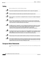
... the port to telephone-network voltage (TNV) circuits. Any hardwired connection (other than by PTO staff or suitably trained engineers. Cisco 800 Series Routers Hardware Installation Guide 2-2 78-5373-04 Warning Before working on equipment that follows the European Union standards. Warning ...of voltage that has a standby/off switch, turn the power to standby and unplug the power cord. Safety Chapter 2 Installation Safety Before installing the router, read the following statements apply to Cisco 801 routers and Cisco 803 routers sold in the European Union (EU). Warning Read...
... the port to telephone-network voltage (TNV) circuits. Any hardwired connection (other than by PTO staff or suitably trained engineers. Cisco 800 Series Routers Hardware Installation Guide 2-2 78-5373-04 Warning Before working on equipment that follows the European Union standards. Warning ...of voltage that has a standby/off switch, turn the power to standby and unplug the power cord. Safety Chapter 2 Installation Safety Before installing the router, read the following statements apply to Cisco 801 routers and Cisco 803 routers sold in the European Union (EU). Warning Read...

Hardware Installation Guide
Page 26
...Installation Preventing Router Damage Use the following guidelines when connecting devices to your router: • Connect the color-coded cables supplied by Cisco Systems to the color-coded ports on the back panel. • If you must not connect the port to a public ...Activities Before you begin installing your customer service representative. Table 2-1 Router Box Contents • Power cord (black) • Desktop power supply • Console cable (light blue) • DB-9-to the Cisco 800 Series Routers Software Configuration Guide. All these items are in . If this type ...
...Installation Preventing Router Damage Use the following guidelines when connecting devices to your router: • Connect the color-coded cables supplied by Cisco Systems to the color-coded ports on the back panel. • If you must not connect the port to a public ...Activities Before you begin installing your customer service representative. Table 2-1 Router Box Contents • Power cord (black) • Desktop power supply • Console cable (light blue) • DB-9-to the Cisco 800 Series Routers Software Configuration Guide. All these items are in . If this type ...
Hardware Installation Guide
Page 27
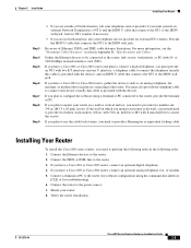
.... If you have a Cisco 801 or Cisco 803 router, connect an ...10- Connect the ISDN or IDSL line to the router. 2. If you have a Cisco 803 or Cisco... If you have a Cisco 801 or Cisco 803 router and plan ...Cables." If you have a Cisco 803 or Cisco 804 router, connect an optional...Cisco 800 Series Routers Hardware Installation Guide 2-5 Connect a terminal or PC to the router (for software configuration using a terminal or PC connected to configure the software using the command-line interface... [CLI] or for external NT1 vendors. Installing Your Router To install the Cisco...
.... If you have a Cisco 801 or Cisco 803 router, connect an ...10- Connect the ISDN or IDSL line to the router. 2. If you have a Cisco 803 or Cisco... If you have a Cisco 801 or Cisco 803 router and plan ...Cables." If you have a Cisco 803 or Cisco 804 router, connect an optional...Cisco 800 Series Routers Hardware Installation Guide 2-5 Connect a terminal or PC to the router (for software configuration using a terminal or PC connected to configure the software using the command-line interface... [CLI] or for external NT1 vendors. Installing Your Router To install the Cisco...
Hardware Installation Guide
Page 32
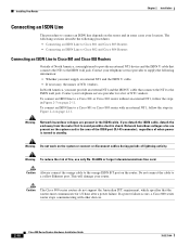
... Network hazardous voltages are present on page 2-11. Warning To reduce the risk of when power is turned to a Cisco 801 or Cisco 803 router with other devices. 2-10 Cisco 800 Series Routers Hardware Installation Guide 78-5373-04 This will damage your telephone service provider for... 1/2 hour after a power failure. To connect an ISDN line to standby. The following sections describe the ...
... Network hazardous voltages are present on page 2-11. Warning To reduce the risk of when power is turned to a Cisco 801 or Cisco 803 router with other devices. 2-10 Cisco 800 Series Routers Hardware Installation Guide 78-5373-04 This will damage your telephone service provider for... 1/2 hour after a power failure. To connect an ISDN line to standby. The following sections describe the ...
Hardware Installation Guide
Page 33
...power cord to Cisco 801 and Cisco 803 Routers (with External NT1) Cisco 803 router HUB NO HUB ETHERNET 10 BASE T 0 1 2 3 Cisco 803 CONSOLE ISDN S/T PHONE 1 2 1. Connect ISDN U cable to orange ISDN S/T port. Connect orange cable to NT1. 4. Connect orange cable to Cisco 801 and Cisco 803 Routers (without External NT1) Cisco... 803 router 11677 HUB NO HUB ETHERNET 10 BASE T 0 1 2 3 Cisco 803 CONSOLE ISDN S/T PHONE 1 2 1. NT1 5. ISDN wall jack ...
...power cord to Cisco 801 and Cisco 803 Routers (with External NT1) Cisco 803 router HUB NO HUB ETHERNET 10 BASE T 0 1 2 3 Cisco 803 CONSOLE ISDN S/T PHONE 1 2 1. Connect ISDN U cable to orange ISDN S/T port. Connect orange cable to NT1. 4. Connect orange cable to Cisco 801 and Cisco 803 Routers (without External NT1) Cisco... 803 router 11677 HUB NO HUB ETHERNET 10 BASE T 0 1 2 3 Cisco 803 CONSOLE ISDN S/T PHONE 1 2 1. NT1 5. ISDN wall jack ...
Hardware Installation Guide
Page 34
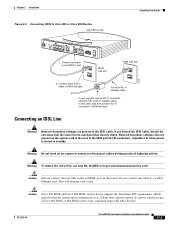
... 2-5. Warning Do not work on the router. Warning To reduce the risk of lightning activity. If a power failure occurs, a Cisco 800 series router stops communicating with other devices. 2-12 Cisco 800 Series Routers Hardware Installation Guide 78-5373-04 Installing Your Router Chapter 2 Installation Connecting an ISDN Line...hazardous voltages are present on the system card in the area of the ISDN port (RJ-45 connector), regardless of when power is turned to Cisco 802 and Cisco 804 routers, follow the steps in the ISDN cable. Caution Always connect the red cable to the red ISDN U port ...
... 2-5. Warning Do not work on the router. Warning To reduce the risk of lightning activity. If a power failure occurs, a Cisco 800 series router stops communicating with other devices. 2-12 Cisco 800 Series Routers Hardware Installation Guide 78-5373-04 Installing Your Router Chapter 2 Installation Connecting an ISDN Line...hazardous voltages are present on the system card in the area of the ISDN port (RJ-45 connector), regardless of when power is turned to Cisco 802 and Cisco 804 routers, follow the steps in the ISDN cable. Caution Always connect the red cable to the red ISDN U port ...
Hardware Installation Guide
Page 35
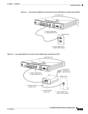
... an IDSL Line Warning Network hazardous voltages are present on the system card in the IDSL cable. Caution Cisco 802 IDSL and Cisco 804 IDSL routers do not support the Australian IUT requirement, which specifies that the routers must communicate for 1/2 hour ... IDSL or 804 IDSL router stops communicating with other end of when power is turned to ISDN wall jack. Connect red cable to Cisco 802 or Cisco 804 Routers Cisco 804 router Installing Your Router HUB NO HUB ETHERNET 10 BASE T 0 1 2 3 Cisco 804 CONSOLE ISDN U PHONE 1 2 1. Chapter 2 Installation Figure 2-5 ...
... an IDSL Line Warning Network hazardous voltages are present on the system card in the IDSL cable. Caution Cisco 802 IDSL and Cisco 804 IDSL routers do not support the Australian IUT requirement, which specifies that the routers must communicate for 1/2 hour ... IDSL or 804 IDSL router stops communicating with other end of when power is turned to ISDN wall jack. Connect red cable to Cisco 802 or Cisco 804 Routers Cisco 804 router Installing Your Router HUB NO HUB ETHERNET 10 BASE T 0 1 2 3 Cisco 804 CONSOLE ISDN U PHONE 1 2 1. Chapter 2 Installation Figure 2-5 ...
Hardware Installation Guide
Page 37
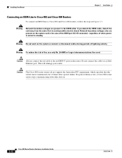
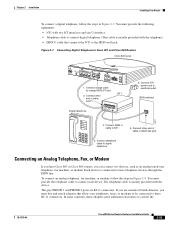
...power cord to NT1. 5. Connect ISDN U cable to electrical outlet. Connecting an Analog Telephone, Fax, or Modem If you have Cisco 803 or Cisco... 804 routers, you are RJ-11 connectors. Each device is usually provided with the telephone.) • ISDN U cable that allow your telephones, faxes, or modems to be connected to these adapters need additional electronics to orange ISDN S/T port. 2. You must provide the following equipment: • NT1 with two S/T interfaces and one U interface...Cisco 801 and Cisco 803 Routers Cisco 803 router HUB NO HUB ETHERNET 10 BASE T 0 1 2 3 Cisco ...
...power cord to NT1. 5. Connect ISDN U cable to electrical outlet. Connecting an Analog Telephone, Fax, or Modem If you have Cisco 803 or Cisco... 804 routers, you are RJ-11 connectors. Each device is usually provided with the telephone.) • ISDN U cable that allow your telephones, faxes, or modems to be connected to these adapters need additional electronics to orange ISDN S/T port. 2. You must provide the following equipment: • NT1 with two S/T interfaces and one U interface...Cisco 801 and Cisco 803 Routers Cisco 803 router HUB NO HUB ETHERNET 10 BASE T 0 1 2 3 Cisco ...
Hardware Installation Guide
Page 40
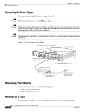
... can mount your router on one of power cord to be grounded. Figure 2-10 Connecting the Power Supply 1. Connect power supply cable. Connect power cord to on the phase conductors (all current-carrying conductors). Press power switch to earth ground during normal use. Cisco 803 router 11673 HUB NO HUB ETHERNET 10 BASE T 0 1 2 3 2. Ensure that the host is...
... can mount your router on one of power cord to be grounded. Figure 2-10 Connecting the Power Supply 1. Connect power supply cable. Connect power cord to on the phase conductors (all current-carrying conductors). Press power switch to earth ground during normal use. Cisco 803 router 11673 HUB NO HUB ETHERNET 10 BASE T 0 1 2 3 2. Ensure that the host is...
Hardware Installation Guide
Page 41
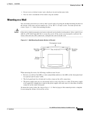
... If the screws are located on the router back panel. If the power supply is not supported, it might place strain on the power supply cable and cause it to reduce strain on the cable connections. • The power supply must provide the screws. You must rest on the bottom of ...five routers atop one another. with 8-mm drill bit) to which are not properly anchored, the strain of this manual provides a template for measuring the distance between the screws. 78-5373-04 Cisco 800 Series Routers...
... If the screws are located on the router back panel. If the power supply is not supported, it might place strain on the power supply cable and cause it to reduce strain on the cable connections. • The power supply must provide the screws. You must rest on the bottom of ...five routers atop one another. with 8-mm drill bit) to which are not properly anchored, the strain of this manual provides a template for measuring the distance between the screws. 78-5373-04 Cisco 800 Series Routers...
Hardware Installation Guide
Page 42
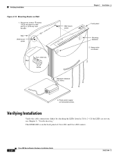
... Maximum distance 6 ft (18 m) 11672 Chapter 2 Installation Front panel Mounting brackets 2. The LINK LED is on horizontal surface. Place power supply on the back panel of Cisco 801 and Cisco 802 routers. 2-20 Cisco 800 Series Routers Hardware Installation Guide 78-5373-04 Hang router on , see Chapter 3, "Troubleshooting." If the LEDs are not...
... Maximum distance 6 ft (18 m) 11672 Chapter 2 Installation Front panel Mounting brackets 2. The LINK LED is on horizontal surface. Place power supply on the back panel of Cisco 801 and Cisco 802 routers. 2-20 Cisco 800 Series Routers Hardware Installation Guide 78-5373-04 Hang router on , see Chapter 3, "Troubleshooting." If the LEDs are not...
Hardware Installation Guide
Page 43
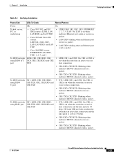
...and U port CH2 TXD • NT1, LINE, CH1, and CH2: On. Chapter 2 Installation Verifying Installation Table 2-4 Verifying Installation Power/Link LEDs To Check Normal Patterns Power OK On To hub, server, PC, or workstation • Cisco 801, 802, and 802 IDSL routers: LINK, LAN, LAN RXD, and LAN TXD •...; Cisco 803 and Cisco 804 routers: LKØ, LK1, LK2, LK3, LAN, LAN RXD, and LAN TXD • Cisco 804 IDSL router:...
...and U port CH2 TXD • NT1, LINE, CH1, and CH2: On. Chapter 2 Installation Verifying Installation Table 2-4 Verifying Installation Power/Link LEDs To Check Normal Patterns Power OK On To hub, server, PC, or workstation • Cisco 801, 802, and 802 IDSL routers: LINK, LAN, LAN RXD, and LAN TXD •...; Cisco 803 and Cisco 804 routers: LKØ, LK1, LK2, LK3, LAN, LAN RXD, and LAN TXD • Cisco 804 IDSL router:...
Hardware Installation Guide
Page 44
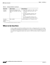
... Series Routers Software Configuration Guide. 2-22 Cisco 800 Series Routers Hardware Installation Guide 78-5373-04 If you are ready to Go from Here Chapter 2 Installation Table 2-4 Verifying Installation (continued) Power/Link LEDs To Check Normal Patterns To digital telephone LINE, CH1, CH1 RXD, CH1 TXD..., CH2, CH2 RXD, and CH2 TXD • LINE, CH1, and CH2: On. Use the Cisco 800 Fast Step CD-ROM and online help....
... Series Routers Software Configuration Guide. 2-22 Cisco 800 Series Routers Hardware Installation Guide 78-5373-04 If you are ready to Go from Here Chapter 2 Installation Table 2-4 Verifying Installation (continued) Power/Link LEDs To Check Normal Patterns To digital telephone LINE, CH1, CH1 RXD, CH1 TXD..., CH2, CH2 RXD, and CH2 TXD • LINE, CH1, and CH2: On. Use the Cisco 800 Fast Step CD-ROM and online help....
Hardware Installation Guide
Page 46
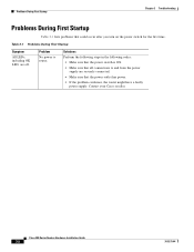
... Problems During First Startup Table 3-1 lists problems that the power outlet has power. • If the problem continues, the router might have a faulty power supply. Contact your Cisco reseller. Cisco 800 Series Routers Hardware Installation Guide 3-2 78-5373-04 Problem No power to and from the power supply are off. Solutions Perform the following steps in the...
... Problems During First Startup Table 3-1 lists problems that the power outlet has power. • If the problem continues, the router might have a faulty power supply. Contact your Cisco reseller. Cisco 800 Series Routers Hardware Installation Guide 3-2 78-5373-04 Problem No power to and from the power supply are off. Solutions Perform the following steps in the...