
Hardware Installation Guide
Page 18
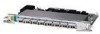
... power supply. Connecting the port to a public network that follows the European Union standards. Power switch l = On. = Standby or no power output. 11666 LINK HUB NO HUB ETHERNET 10 BASE T Cisco 801 CONSOLE ISDN S/T Cable lock Use cable lock to external NT1 or ISDN wall jack. If... the symbol of suitability ( ) appears above a port, you can cause severe injury or damage your router. device connection. Figure 1-4 Cisco 801 Router Back Panel ...
... power supply. Connecting the port to a public network that follows the European Union standards. Power switch l = On. = Standby or no power output. 11666 LINK HUB NO HUB ETHERNET 10 BASE T Cisco 801 CONSOLE ISDN S/T Cable lock Use cable lock to external NT1 or ISDN wall jack. If... the symbol of suitability ( ) appears above a port, you can cause severe injury or damage your router. device connection. Figure 1-4 Cisco 801 Router Back Panel ...

Hardware Installation Guide
Page 19
...jack. Telephone ports Connect to physically secure router. Power switch l = On. = Standby or no power output. PHONE 1 2 Locking power connector Connect power supply. 78-5373-04 Cisco 800 Series Routers Hardware Installation Guide 1-5 Power switch l = On. = Standby or no power output...Connect PC or terminal. Locking power connector Connect power supply. 11667 Figure 1-6 Cisco 803 Router Back Panel Ethernet ports Connect Ethernet network devices. HUB NO HUB ETHERNET 10 BASE T 0 1 2 3 Cisco 803 CONSOLE ISDN S/T HUB/NO HUB button (for Ethernet port 0) Determines ...
...jack. Telephone ports Connect to physically secure router. Power switch l = On. = Standby or no power output. PHONE 1 2 Locking power connector Connect power supply. 78-5373-04 Cisco 800 Series Routers Hardware Installation Guide 1-5 Power switch l = On. = Standby or no power output...Connect PC or terminal. Locking power connector Connect power supply. 11667 Figure 1-6 Cisco 803 Router Back Panel Ethernet ports Connect Ethernet network devices. HUB NO HUB ETHERNET 10 BASE T 0 1 2 3 Cisco 803 CONSOLE ISDN S/T HUB/NO HUB button (for Ethernet port 0) Determines ...

Hardware Installation Guide
Page 20
... physically secure router. Console port Connect PC or terminal. Power switch l = On. = Standby or no power output. Back Panels Chapter 1 Overview Figure 1-7 Cisco 804 Router Back Panel Ethernet ports Connect Ethernet network devices. LINK TO TO HUB PC ETHERNET 10 BASE T CONSOLE Cisco 802 IDSL IDSL Cable lock Use cable lock to IDSL wall...
... physically secure router. Console port Connect PC or terminal. Power switch l = On. = Standby or no power output. Back Panels Chapter 1 Overview Figure 1-7 Cisco 804 Router Back Panel Ethernet ports Connect Ethernet network devices. LINK TO TO HUB PC ETHERNET 10 BASE T CONSOLE Cisco 802 IDSL IDSL Cable lock Use cable lock to IDSL wall...

Hardware Installation Guide
Page 21
... LK3 Green Green Green Green Green ETHERNET Green 1, 2, 3, 4 Function On when power is supplied to synchronize. On when the ISDN interface and the ISDN terminal device are synchronized. Blinks when the connection has a problem. Not applicable for Ethernet device connection. Blinks when an ... HUB PC ETHERNET 10 BASE T 1 2 3 4 TO HUB/TO PC (for Ethernet port 1) Determines cable type for Cisco 801 and 803 routers. Locking power connector Connect power supply. On when the internal NT1 and the ISDN switch are synchronized. Cisco 804 IDSL routers only. Cisco 803 and 804 ...
... LK3 Green Green Green Green Green ETHERNET Green 1, 2, 3, 4 Function On when power is supplied to synchronize. On when the ISDN interface and the ISDN terminal device are synchronized. Blinks when the connection has a problem. Not applicable for Ethernet device connection. Blinks when an ... HUB PC ETHERNET 10 BASE T 1 2 3 4 TO HUB/TO PC (for Ethernet port 1) Determines cable type for Cisco 801 and 803 routers. Locking power connector Connect power supply. On when the internal NT1 and the ISDN switch are synchronized. Cisco 804 IDSL routers only. Cisco 803 and 804 ...
Hardware Installation Guide
Page 24
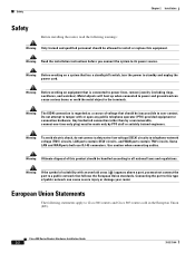
... (PTO)-provided equipment or connection hardware. Use caution when connecting cables. Warning If the symbol of voltage that has a standby/off switch, turn the power to user contact. Warning To avoid electric shock, do not connect safety extra-low voltage (SELV) circuits to its...including rings, necklaces, and watches). Warning Ultimate disposal of public network can cause serious burns or weld the metal object to Cisco 801 routers and Cisco 803 routers sold in the European Union (EU). Safety Chapter 2 Installation Safety Before installing the router, read the following ...
... (PTO)-provided equipment or connection hardware. Use caution when connecting cables. Warning If the symbol of voltage that has a standby/off switch, turn the power to user contact. Warning To avoid electric shock, do not connect safety extra-low voltage (SELV) circuits to its...including rings, necklaces, and watches). Warning Ultimate disposal of public network can cause serious burns or weld the metal object to Cisco 801 routers and Cisco 803 routers sold in the European Union (EU). Safety Chapter 2 Installation Safety Before installing the router, read the following ...
Hardware Installation Guide
Page 40
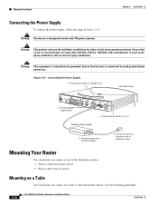
... a Table You can mount your router on the building's installation for short-circuit (overcurrent) protection. Figure 2-10 Connecting the Power Supply 1. Press power switch to standby ( ). Press power switch to on ( ). Cisco 803 router 11673 HUB NO HUB ETHERNET 10 BASE T 0 1 2 3 2. Use the following surfaces: • Table or other horizontal surface • Wall or other...
... a Table You can mount your router on the building's installation for short-circuit (overcurrent) protection. Figure 2-10 Connecting the Power Supply 1. Press power switch to standby ( ). Press power switch to on ( ). Cisco 803 router 11673 HUB NO HUB ETHERNET 10 BASE T 0 1 2 3 2. Use the following surfaces: • Table or other horizontal surface • Wall or other...
Hardware Installation Guide
Page 46
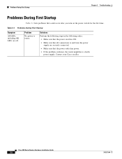
Contact your Cisco reseller. Cisco 800 Series Routers Hardware Installation Guide 3-2 78-5373-04 Solutions Perform the following steps in the following order: • Make sure that the power switch is ON. • Make sure that all connections to router. Problems During First Startup Chapter 3 Troubleshooting Problems During First Startup Table 3-1 lists problems that... 3-1 Problems During First Startup Symptom All LEDs, including OK LED, are securely connected. • Make sure that could occur after you turn on the power switch for the first time.
Contact your Cisco reseller. Cisco 800 Series Routers Hardware Installation Guide 3-2 78-5373-04 Solutions Perform the following steps in the following order: • Make sure that the power switch is ON. • Make sure that all connections to router. Problems During First Startup Chapter 3 Troubleshooting Problems During First Startup Table 3-1 lists problems that... 3-1 Problems During First Startup Symptom All LEDs, including OK LED, are securely connected. • Make sure that could occur after you turn on the power switch for the first time.
Hardware Installation Guide
Page 53
... through the ISDN port on these routers. Cisco 802 and Cisco 804 routers have an ISDN U port, and Cisco 802 IDSL and Cisco 804 IDSL routers have an ISDN S/T port. In North America, telephone service providers typically provide a U interface. The U interface is a two-wire (single pair) interface from the phone switch that supports full-duplex data transfer over...
... through the ISDN port on these routers. Cisco 802 and Cisco 804 routers have an ISDN U port, and Cisco 802 IDSL and Cisco 804 IDSL routers have an ISDN S/T port. In North America, telephone service providers typically provide a U interface. The U interface is a two-wire (single pair) interface from the phone switch that supports full-duplex data transfer over...
Hardware Installation Guide
Page 63
... pair for transmitting data and the other for circuit-switched communication of voice, video, and data. This cable connects two similar devices, for basic configurations and verification of the router software configuration. C Cisco 800 Fast Step Application A Windows 95-, Windows 98...-T The 10-Mbps baseband Ethernet specification that uses two pairs of twisted-pair cabling (Category 3 or 5): one data channel (D channel) for receiving data. B BRI Basic Rate Interface. crossover Ethernet cable A cable that must be refreshed periodically. E 78-5373-04 Cisco 800 Series...
... pair for transmitting data and the other for circuit-switched communication of voice, video, and data. This cable connects two similar devices, for basic configurations and verification of the router software configuration. C Cisco 800 Fast Step Application A Windows 95-, Windows 98...-T The 10-Mbps baseband Ethernet specification that uses two pairs of twisted-pair cabling (Category 3 or 5): one data channel (D channel) for receiving data. B BRI Basic Rate Interface. crossover Ethernet cable A cable that must be refreshed periodically. E 78-5373-04 Cisco 800 Series...
Hardware Installation Guide
Page 68
... illustrated 1-6, 1-7 installation verifying 2-20 warnings 2-2 ISDN concepts A-1 ISDN line, connecting 2-10 to 2-13 ISDN S/T port described 1-2 illustrated 1-5 ISDN U port described 1-2 illustrated 1-5, 1-6 L LEDs IN-2 Cisco 800 Series Routers Hardware Installation Guide described 1-7 illustrated 1-3 to 1-6 locking power connector, ... 1-3 power problems 3-2 specifications B-1 verifying 2-20 power supply connecting 2-18 power switch illustrated 1-4 to 2-4 78-5373-04 to 1-7 preinstallation activities 2-4 R router concepts A-1 damage, preventing 2-4 features 1-2 ports 1-3 unpacking 2-4, ??
... illustrated 1-6, 1-7 installation verifying 2-20 warnings 2-2 ISDN concepts A-1 ISDN line, connecting 2-10 to 2-13 ISDN S/T port described 1-2 illustrated 1-5 ISDN U port described 1-2 illustrated 1-5, 1-6 L LEDs IN-2 Cisco 800 Series Routers Hardware Installation Guide described 1-7 illustrated 1-3 to 1-6 locking power connector, ... 1-3 power problems 3-2 specifications B-1 verifying 2-20 power supply connecting 2-18 power switch illustrated 1-4 to 2-4 78-5373-04 to 1-7 preinstallation activities 2-4 R router concepts A-1 damage, preventing 2-4 features 1-2 ports 1-3 unpacking 2-4, ??