Installation Guide
Page 3
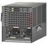
... to an employee's residence. When such trouble occurs, the user may arise. A core component of the Cisco unified wireless solution, these controllers deliver wireless security, intrusion detection, radio management, quality of the Cisco 5508 Wireless Controller. 78-18998-01 Cisco 5500 Series Wireless Controller Installation Guide 3 In order to best use this equipment is used in a domestic environment, radio disturbance may...
... to an employee's residence. When such trouble occurs, the user may arise. A core component of the Cisco unified wireless solution, these controllers deliver wireless security, intrusion detection, radio management, quality of the Cisco 5508 Wireless Controller. 78-18998-01 Cisco 5500 Series Wireless Controller Installation Guide 3 In order to best use this equipment is used in a domestic environment, radio disturbance may...
Installation Guide
Page 4
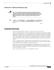
... console ports. EIA/TIA-232 Depending on any PC connected to the Release Notes for Cisco Wireless LAN Controllers and Lightweight Access Points for information about downloading the latest Cisco Windows USB Console Driver, refer to the console port. USB Console The USB console port...port, the other is not installed, prompts guide you through a simple installation process. Controller Overview Figure 1 Front Panel 12 345 6 Cisco 5500 Series Wireless Controller RP SP USB0 USB1 EN EN 7 12 3 4 56 7 8 Model 5508 PS1 PS2 SYS ALM 8 9 10 251197 1 Redundant port (RP) for the...
... console ports. EIA/TIA-232 Depending on any PC connected to the Release Notes for Cisco Wireless LAN Controllers and Lightweight Access Points for information about downloading the latest Cisco Windows USB Console Driver, refer to the console port. USB Console The USB console port...port, the other is not installed, prompts guide you through a simple installation process. Controller Overview Figure 1 Front Panel 12 345 6 Cisco 5500 Series Wireless Controller RP SP USB0 USB1 EN EN 7 12 3 4 56 7 8 Model 5508 PS1 PS2 SYS ALM 8 9 10 251197 1 Redundant port (RP) for the...
Installation Guide
Page 12
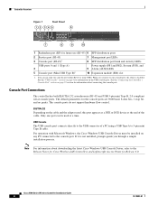
... each bracket are used (top, left, and right). All connections must work together to install the controller. Note Only three of the controller chassis, and place the chassis on each of the corners on the bottom of the four holes on any secure horizontal surface. Two... Installing the Front Brackets RP SP USB0 USB1 CONSOLE EN EN Cisco 5500 Series Wireless Controller 12 34 56 78 Model 5508 PS1 PS2 SYS ACT 1 Front bracket 12 2 M4x0.7 x 8mm flat head screws 251200 Cisco 5500 Series Wireless Controller Installation Guide 12 78-18998-01 Follow the same steps to attach...
... each bracket are used (top, left, and right). All connections must work together to install the controller. Note Only three of the controller chassis, and place the chassis on each of the corners on the bottom of the four holes on any secure horizontal surface. Two... Installing the Front Brackets RP SP USB0 USB1 CONSOLE EN EN Cisco 5500 Series Wireless Controller 12 34 56 78 Model 5508 PS1 PS2 SYS ACT 1 Front bracket 12 2 M4x0.7 x 8mm flat head screws 251200 Cisco 5500 Series Wireless Controller Installation Guide 12 78-18998-01 Follow the same steps to attach...
Installation Guide
Page 13
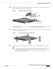
... the Rack (Front) RP SP USB0 USB1 CONSOLE EN EN Cisco 5500 Series Wireless Controller 12 34 56 78 Model 5508 PS1 PS2 SYS ACT 251202 Step 4 Measure the distance between the front and rear rack rails and select the proper slide-...-01 Cisco 5500 Series Wireless Controller Installation Guide 13 Unpacking and Installing the Controller Step 2 Attach one of the controller chassis into the rack using three M3 screws (see Figure 6). Figure 5 Installing the Rear Bracket Adapters RP SP USB0 USB1 CONSOLE EN EN Cisco 5500 Series Wireless Controller 12 34 56 78 Model 5508 PS1 PS2...
... the Rack (Front) RP SP USB0 USB1 CONSOLE EN EN Cisco 5500 Series Wireless Controller 12 34 56 78 Model 5508 PS1 PS2 SYS ACT 251202 Step 4 Measure the distance between the front and rear rack rails and select the proper slide-...-01 Cisco 5500 Series Wireless Controller Installation Guide 13 Unpacking and Installing the Controller Step 2 Attach one of the controller chassis into the rack using three M3 screws (see Figure 6). Figure 5 Installing the Rear Bracket Adapters RP SP USB0 USB1 CONSOLE EN EN Cisco 5500 Series Wireless Controller 12 34 56 78 Model 5508 PS1 PS2...

Installation Guide
Page 14
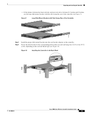
... with Tabs Facing Rear of the Controller RP SP USB0 USB1 CONSOLE EN EN Cisco 5500 Series Wireless Controller 12 34 56 78 Model 5508 PS1 PS2 SYS ACT RP SP USB0 USB1 CONSOLE EN EN Cisco 5500 Series Wireless Controller 12 34 56 78 Model 5508 PS1 PS2 SYS ACT 251237 Cisco 5500 Series Wireless Controller Installation Guide 14 78-18998...
... with Tabs Facing Rear of the Controller RP SP USB0 USB1 CONSOLE EN EN Cisco 5500 Series Wireless Controller 12 34 56 78 Model 5508 PS1 PS2 SYS ACT RP SP USB0 USB1 CONSOLE EN EN Cisco 5500 Series Wireless Controller 12 34 56 78 Model 5508 PS1 PS2 SYS ACT 251237 Cisco 5500 Series Wireless Controller Installation Guide 14 78-18998...
Installation Guide
Page 15
... Brackets with the tabs facing the rear of the Controller RP SP USB0 USB1 CONSOLE EN EN Cisco 5500 Series Wireless Controller 12 34 56 78 Model 5508 PS1 PS2 SYS ACT 251238 RP SP USB0 USB1 CONSOLE EN EN Cisco 5500 Series Wireless Controller 12 34 56 78 Model 5508 PS1 PS2 SYS ACT Step 5 Step 6 Install the...
... Brackets with the tabs facing the rear of the Controller RP SP USB0 USB1 CONSOLE EN EN Cisco 5500 Series Wireless Controller 12 34 56 78 Model 5508 PS1 PS2 SYS ACT 251238 RP SP USB0 USB1 CONSOLE EN EN Cisco 5500 Series Wireless Controller 12 34 56 78 Model 5508 PS1 PS2 SYS ACT Step 5 Step 6 Install the...

Installation Guide
Page 16
...work together to install the controller. Figure 11 Installing the Cable Guide RP SP USB0 USB1 CONSOLE EN EN Cisco 5500 Series Wireless Controller 12 34 56 78 Model 5508 PS1 PS2 SYS ACT 251240 Installing the Controller in the rack. Note Only three of the switch and the other devices ...installed in a 2-Post Rack-Flush Mount Caution The controller weighs 20 lbs (9.1 kg)...
...work together to install the controller. Figure 11 Installing the Cable Guide RP SP USB0 USB1 CONSOLE EN EN Cisco 5500 Series Wireless Controller 12 34 56 78 Model 5508 PS1 PS2 SYS ACT 251240 Installing the Controller in the rack. Note Only three of the switch and the other devices ...installed in a 2-Post Rack-Flush Mount Caution The controller weighs 20 lbs (9.1 kg)...
Installation Guide
Page 17
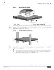
... the front of the switch and the other devices installed in the rack. 78-18998-01 Cisco 5500 Series Wireless Controller Installation Guide 17 Figure 13 Installing the Controller in the Rack RP SP USB0 USB1 CONSOLE EN EN Cisco 5500 Series Wireless Controller 12 34 56 78 Model 5508 PS1 PS2 SYS ACT ...274464 Step 3 (Optional) Use the supplied M4x0.7 x 20mm pan head screw to attach the cable guide to prevent the cables from obscuring the front panel of the controller chassis into the ...
... the front of the switch and the other devices installed in the rack. 78-18998-01 Cisco 5500 Series Wireless Controller Installation Guide 17 Figure 13 Installing the Controller in the Rack RP SP USB0 USB1 CONSOLE EN EN Cisco 5500 Series Wireless Controller 12 34 56 78 Model 5508 PS1 PS2 SYS ACT ...274464 Step 3 (Optional) Use the supplied M4x0.7 x 20mm pan head screw to attach the cable guide to prevent the cables from obscuring the front panel of the controller chassis into the ...

Installation Guide
Page 18
... the front brackets to ground the chassis in a 2-Post Rack-Mid-Mount Caution The controller weighs 20 lbs (9.1 kg) with both power supplies installed. All connections must work together to the opposite side. Cisco 5500 Series Wireless Controller Installation Guide 18 78-18998-01 ... ground the chassis using your own grounding lug. Unpacking and Installing the Controller Figure 14 Installing the Cable Guide RP SP USB0 USB1 CONSOLE EN EN Cisco 5500 Series Wireless Controller 12 34 56 78 Model 5508 PS1 PS2 SYS ACT 205855 Installing the Controller in a different...
... the front brackets to ground the chassis in a 2-Post Rack-Mid-Mount Caution The controller weighs 20 lbs (9.1 kg) with both power supplies installed. All connections must work together to the opposite side. Cisco 5500 Series Wireless Controller Installation Guide 18 78-18998-01 ... ground the chassis using your own grounding lug. Unpacking and Installing the Controller Figure 14 Installing the Cable Guide RP SP USB0 USB1 CONSOLE EN EN Cisco 5500 Series Wireless Controller 12 34 56 78 Model 5508 PS1 PS2 SYS ACT 205855 Installing the Controller in a different...
Installation Guide
Page 19
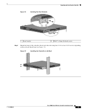
Figure 15 Installing the Front Brackets Unpacking and Installing the Controller RP SP USB0 USB1 CONSOLE EN EN Cisco 5500 Series Wireless Controller 12 34 56 78 Model 5508 PS1 PS2 SYS ACT 1 2 274465 1 Front bracket 2 M4x0.7 x 8mm flat head screws Step 2 Mount the front of the controller chassis into the rack using four 12-24 or four...
Figure 15 Installing the Front Brackets Unpacking and Installing the Controller RP SP USB0 USB1 CONSOLE EN EN Cisco 5500 Series Wireless Controller 12 34 56 78 Model 5508 PS1 PS2 SYS ACT 1 2 274465 1 Front bracket 2 M4x0.7 x 8mm flat head screws Step 2 Mount the front of the controller chassis into the rack using four 12-24 or four...

Installation Guide
Page 20
... Caution We recommend grounding the chassis, even if the rack is provided on the right side of Chassis Ground on the Controller (Right Side) 251241 RP SP USB0 USB1 CONSOLE EN EN Cisco 5500 Series Wireless Controller 12 34 56 78 Model 5508 PS1 PS2 SYS ACT Warning When... installing or replacing the unit, the ground connection must be grounded. Cisco 5500 Series Wireless Controller Installation ...
... Caution We recommend grounding the chassis, even if the rack is provided on the right side of Chassis Ground on the Controller (Right Side) 251241 RP SP USB0 USB1 CONSOLE EN EN Cisco 5500 Series Wireless Controller 12 34 56 78 Model 5508 PS1 PS2 SYS ACT Warning When... installing or replacing the unit, the ground connection must be grounded. Cisco 5500 Series Wireless Controller Installation ...

Installation Guide
Page 21
.... Figure 18 ESD Wrist Strap Connector Location RP SP USB0 USB1 CONSOLE EN EN Cisco 5500 Series Wireless Controller 12 34 56 78 Model 5508 PS1 PS2 SYS ACT 251239 78-18998-01 Cisco 5500 Series Wireless Controller Installation Guide 21 Only copper conductors (wires) must be used and the copper conductor...that the lug and cable do not interfere with National Electrical Code (NEC) for the connector location) • Any unpainted surface on the chassis. Use the crimping tool to one of the following: • ESD wrist strap connector (see Figure 18 for ampacity. Connect the strap ...
.... Figure 18 ESD Wrist Strap Connector Location RP SP USB0 USB1 CONSOLE EN EN Cisco 5500 Series Wireless Controller 12 34 56 78 Model 5508 PS1 PS2 SYS ACT 251239 78-18998-01 Cisco 5500 Series Wireless Controller Installation Guide 21 Only copper conductors (wires) must be used and the copper conductor...that the lug and cable do not interfere with National Electrical Code (NEC) for the connector location) • Any unpainted surface on the chassis. Use the crimping tool to one of the following: • ESD wrist strap connector (see Figure 18 for ampacity. Connect the strap ...