
Installation Guide
Page 5
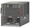
... Note An amber LED could indicate an error or a possible hardware failure. 78-18998-01 Cisco 5500 Series Wireless Controller Installation Guide 5 Controller Overview With the Cisco Windows USB Console Driver, you can plug and unplugg the USB cable from the USB port... 2 shows the back panel with 5-pin mini Type B connectors. Figure 2 12 Back Panel 251198 3 4 1 Power supply PS1 2 Power supply PS1 on/off switch 3 Power supply PS1 AC cable connection 5 4 Power supply PS2 slot with blank cover 5 Fan tray Checking the Controller LEDs If your controller is removed from the console port ...
... Note An amber LED could indicate an error or a possible hardware failure. 78-18998-01 Cisco 5500 Series Wireless Controller Installation Guide 5 Controller Overview With the Cisco Windows USB Console Driver, you can plug and unplugg the USB cable from the USB port... 2 shows the back panel with 5-pin mini Type B connectors. Figure 2 12 Back Panel 251198 3 4 1 Power supply PS1 2 Power supply PS1 on/off switch 3 Power supply PS1 AC cable connection 5 4 Power supply PS2 slot with blank cover 5 Fan tray Checking the Controller LEDs If your controller is removed from the console port ...
Installation Guide
Page 6
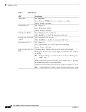
...with failure. When this LED is on . Blinks green: Indicates that a power supply is amber, the power supply shuts down. Note When the PS1 or PS2 LED is installed but does not have AC power. Cisco 5500 Series Wireless Controller Installation Guide 6 78-18998-01 Amber: Present with failure...present. Green: Indicates active aux port. Continuous amber: Indicates that the power supply is in installed correctly and that the power supply is over temperature. Off: Not present. Continuous green: Indicates that the power switch is off . When this LED is on, the RJ-45 console port...
...with failure. When this LED is on . Blinks green: Indicates that a power supply is amber, the power supply shuts down. Note When the PS1 or PS2 LED is installed but does not have AC power. Cisco 5500 Series Wireless Controller Installation Guide 6 78-18998-01 Amber: Present with failure...present. Green: Indicates active aux port. Continuous amber: Indicates that the power supply is in installed correctly and that the power supply is over temperature. Off: Not present. Continuous green: Indicates that the power switch is off . When this LED is on, the RJ-45 console port...

Installation Guide
Page 20
...the unit, the ground connection must always be made first and disconnected last. Figure 17 Location of Chassis Ground on the left side of the controller. Cisco 5500 Series Wireless Controller Installation Guide 20 78-18998-01 You will need to protective earth ground ...AC power cables used to provide power to the chassis must be the grounding type, and the grounding conductors should connect to ground the chassis in a different location on the right side of the chassis in a 2-post rack (see Figure 15), you mid-mounted the chassis in the wire-down position. Caution All power supplies...
...the unit, the ground connection must always be made first and disconnected last. Figure 17 Location of Chassis Ground on the left side of the controller. Cisco 5500 Series Wireless Controller Installation Guide 20 78-18998-01 You will need to protective earth ground ...AC power cables used to provide power to the chassis must be the grounding type, and the grounding conductors should connect to ground the chassis in a different location on the right side of the chassis in a 2-post rack (see Figure 15), you mid-mounted the chassis in the wire-down position. Caution All power supplies...
Installation Guide
Page 22
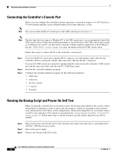
..., 50/60 Hz electrical outlet. you plug the controller into an AC power source, the bootup script initializes the system, verifies the hardware configuration, loads its stored configurations. Follow these steps to run the bootup script and conduct the power-on the power supply. Configure the terminal emulation program for the following parameters: • ...USB console port (see Figure 1). The USB console driver maps to a COM port on page 22. Before performing this test, you should connect your PC; Cisco 5500 Series Wireless Controller Installation Guide 22 78-18998-01
..., 50/60 Hz electrical outlet. you plug the controller into an AC power source, the bootup script initializes the system, verifies the hardware configuration, loads its stored configurations. Follow these steps to run the bootup script and conduct the power-on the power supply. Configure the terminal emulation program for the following parameters: • ...USB console port (see Figure 1). The USB console driver maps to a COM port on page 22. Before performing this test, you should connect your PC; Cisco 5500 Series Wireless Controller Installation Guide 22 78-18998-01

