Installation Guide
Page 4
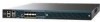
... port (RJ-45) 3 Console port (RJ-45)1 7 Management port LEDs 8 SFP distribution port Link and Activity LEDs USB ports 0 and 1 (Type A) 4 5 Console port (Mini USB Type B)1 Power supply (PS1 and PS2), System (SYS), and 9 Alarm (ALM) LEDs 10 Expansion module (EM) slot 1. The console ports do not support hardware flow control. Controller Overview Figure 1 Front Panel 12 345 6 Cisco 5500 Series Wireless Controller...
... port (RJ-45) 3 Console port (RJ-45)1 7 Management port LEDs 8 SFP distribution port Link and Activity LEDs USB ports 0 and 1 (Type A) 4 5 Console port (Mini USB Type B)1 Power supply (PS1 and PS2), System (SYS), and 9 Alarm (ALM) LEDs 10 Expansion module (EM) slot 1. The console ports do not support hardware flow control. Controller Overview Figure 1 Front Panel 12 345 6 Cisco 5500 Series Wireless Controller...

Installation Guide
Page 5
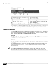
... the USB console port the RJ-45 port becomes inactive. USB Console OS Compatibility • Microsoft Windows 2000, XP, Vista • Apple Mac OS X 10.5.2 • Linux Figure 2 shows the back panel with 5-pin mini Type B connectors. Controller Overview With the Cisco Windows USB Console Driver...Only the 5-pin mini Type B can be used. Note An amber LED could indicate an error or a possible hardware failure. 78-18998-01 Cisco 5500 Series Wireless Controller Installation Guide 5 Figure 2 12 Back Panel 251198 3 4 1 Power supply PS1 2 Power supply PS1 on/off switch 3 Power supply PS1 ...
... the USB console port the RJ-45 port becomes inactive. USB Console OS Compatibility • Microsoft Windows 2000, XP, Vista • Apple Mac OS X 10.5.2 • Linux Figure 2 shows the back panel with 5-pin mini Type B connectors. Controller Overview With the Cisco Windows USB Console Driver...Only the 5-pin mini Type B can be used. Note An amber LED could indicate an error or a possible hardware failure. 78-18998-01 Cisco 5500 Series Wireless Controller Installation Guide 5 Figure 2 12 Back Panel 251198 3 4 1 Power supply PS1 2 Power supply PS1 on/off switch 3 Power supply PS1 ...
Installation Guide
Page 6
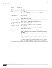
...: Present with failure. Green: Present and enabled. Green: Indicates SFP port is active and link is over temperature. Note Verify that the power cord in failure condition. Cisco 5500 Series Wireless Controller Installation Guide 6 78-18998-01 Amber: Present with failure. Blinks amber...PS1 or PS2 LED is operational. Green: Indicates active aux port. When this LED is off . Controller Overview Table 1 LED Indicators LED RP/SP port USB0/USB1 port Console port (RJ-45) Console port (mini-USB Type B) Distribution ports 1-8 Power supplies (PS1 and PS2) Description Off: Not ...
...: Present with failure. Green: Present and enabled. Green: Indicates SFP port is active and link is over temperature. Note Verify that the power cord in failure condition. Cisco 5500 Series Wireless Controller Installation Guide 6 78-18998-01 Amber: Present with failure. Blinks amber...PS1 or PS2 LED is operational. Green: Indicates active aux port. When this LED is off . Controller Overview Table 1 LED Indicators LED RP/SP port USB0/USB1 port Console port (RJ-45) Console port (mini-USB Type B) Distribution ports 1-8 Power supplies (PS1 and PS2) Description Off: Not ...
Installation Guide
Page 8
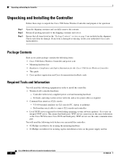
... the shipping container and carefully remove the contents. Network, operating system service network, and access point cables as the Cisco WCS because Cisco WCS and third-party TFTP servers use the same communication port. Package Contents Each access point package contains the following items: • Cisco 5500 Series Wireless Controller and power cord • Mounting hardware kit •...
... the shipping container and carefully remove the contents. Network, operating system service network, and access point cables as the Cisco WCS because Cisco WCS and third-party TFTP servers use the same communication port. Package Contents Each access point package contains the following items: • Cisco 5500 Series Wireless Controller and power cord • Mounting hardware kit •...
Installation Guide
Page 9
... (none or DHCP). • A management interface (DS port or network interface port) IP address. Yes is available at cisco.com. • Status of the 802.11a, 802.11b, 802.11g, and 802.11n networks (enabled or disabled). • Status of radio resource management (RRM) (enabled or disabled). 78-18998-01 Cisco 5500 Series Wireless Controller Installation Guide 9 Refer to local...
... (none or DHCP). • A management interface (DS port or network interface port) IP address. Yes is available at cisco.com. • Status of the 802.11a, 802.11b, 802.11g, and 802.11n networks (enabled or disabled). • Status of radio resource management (RRM) (enabled or disabled). 78-18998-01 Cisco 5500 Series Wireless Controller Installation Guide 9 Refer to local...
Installation Guide
Page 10
...m) of equipment connected to a network through a 1300 nM (LX/LH) fiber-optic link using an LC physical connector. Note These distances depend on the small form factor pluggable (SFP) gigabit converter being used (GLC-SX-MM, SFP-GE-T, or GLC-LH-SM). Cisco 5500 Series Wireless Controller Installation Guide 10 78-18998-01... reliable if you install it in an area that exceeds the maximum recommended ambient temperature of equipment connected to the optional 1000BASE-SX or -LX port: - 722 ft (220 m) when using 160 MHz-km rated 62.5/125 um multimode fiber. - 902 ft (275 m) when using 200 MHz-km ...
...m) of equipment connected to a network through a 1300 nM (LX/LH) fiber-optic link using an LC physical connector. Note These distances depend on the small form factor pluggable (SFP) gigabit converter being used (GLC-SX-MM, SFP-GE-T, or GLC-LH-SM). Cisco 5500 Series Wireless Controller Installation Guide 10 78-18998-01... reliable if you install it in an area that exceeds the maximum recommended ambient temperature of equipment connected to the optional 1000BASE-SX or -LX port: - 722 ft (220 m) when using 160 MHz-km rated 62.5/125 um multimode fiber. - 902 ft (275 m) when using 200 MHz-km ...
Installation Guide
Page 22
... Test When you then need to connect it to a PC that you connect a Windows PC to the USB console port, you are prompted to install the USB console driver. Cisco 5500 Series Wireless Controller Installation Guide 22 78-18998-01 Follow these steps to connect the PC to a COM... port on self test (POST). you plug the controller into an AC power source, the bootup script initializes the system, verifies the...
... Test When you then need to connect it to a PC that you connect a Windows PC to the USB console port, you are prompted to install the USB console driver. Cisco 5500 Series Wireless Controller Installation Guide 22 78-18998-01 Follow these steps to connect the PC to a COM... port on self test (POST). you plug the controller into an AC power source, the bootup script initializes the system, verifies the...

Installation Guide
Page 24
... untagged VLAN) for basic operation using the Startup Wizard, follow these steps: Step 1 When prompted to ensure service access during network downtime. Cisco 5500 Series Wireless Controller Installation Guide 24 78-18998-01 Note The service-port interface controls communications through a dedicated management network to terminate the AutoInstall process, enter yes. Using the Startup Wizard Step 6 If the...
... untagged VLAN) for basic operation using the Startup Wizard, follow these steps: Step 1 When prompted to ensure service access during network downtime. Cisco 5500 Series Wireless Controller Installation Guide 24 78-18998-01 Note The service-port interface controls communications through a dedicated management network to terminate the AutoInstall process, enter yes. Using the Startup Wizard Step 6 If the...
Installation Guide
Page 25
... controller and connectivity to clients, the controller's management interface, and optionally the service-port interface. However, a mobility group facilitates scalable, system-wide mobility and controller redundancy while an RF group facilitates scalable, system-wide dynamic RF management. All of the controllers in -band management ... Step 13 Step 14 Enter the network name, or service set to optimize RRM parameter settings, such as channel and transmit power assignment, for the group. 78-18998-01 Cisco 5500 Series Wireless Controller Installation Guide 25 Using the Startup Wizard...
... controller and connectivity to clients, the controller's management interface, and optionally the service-port interface. However, a mobility group facilitates scalable, system-wide mobility and controller redundancy while an RF group facilitates scalable, system-wide dynamic RF management. All of the controllers in -band management ... Step 13 Step 14 Enter the network name, or service set to optimize RRM parameter settings, such as channel and transmit power assignment, for the group. 78-18998-01 Cisco 5500 Series Wireless Controller Installation Guide 25 Using the Startup Wizard...
Installation Guide
Page 27
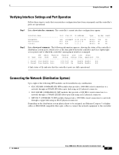
... N/A A link status of the controller's distribution system ports, which serve as the data path between the controller and Cisco lightweight access points and to which the controller's management interface is mapped. Depending on the distribution system physical port to be installed in any combination:.../LX/LH compatible fiber-optic cables to connect the network equipment to the controller. 78-18998-01 Cisco 5500 Series Wireless Controller Installation Guide 27 Using the Startup Wizard Verifying Interface Settings and Port Operation Follow these steps to verify that your interface...
... N/A A link status of the controller's distribution system ports, which serve as the data path between the controller and Cisco lightweight access points and to which the controller's management interface is mapped. Depending on the distribution system physical port to be installed in any combination:.../LX/LH compatible fiber-optic cables to connect the network equipment to the controller. 78-18998-01 Cisco 5500 Series Wireless Controller Installation Guide 27 Using the Startup Wizard Verifying Interface Settings and Port Operation Follow these steps to verify that your interface...
Installation Guide
Page 28
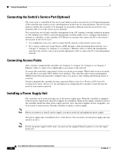
... or a PC running Cisco WCS, a network management tool that enables you must use Category-5, Category-5e, Category-6, or Category-7 Ethernet cables to connect Cisco lightweight access points to the switch's service port in its database. Also, the power supplies are redundant. Refer to the Cisco Wireless LAN Controller Configuration Guide, Release 6.0, for your wireless network. The controller radio resource management (RRM) feature...
... or a PC running Cisco WCS, a network management tool that enables you must use Category-5, Category-5e, Category-6, or Category-7 Ethernet cables to connect Cisco lightweight access points to the switch's service port in its database. Also, the power supplies are redundant. Refer to the Cisco Wireless LAN Controller Configuration Guide, Release 6.0, for your wireless network. The controller radio resource management (RRM) feature...

Data Sheet
Page 4
... 2665 Ethernet-Like Interface types MIB ● RFC 2674 Definitions of Managed Objects for IEEE 802.3 MAUs ● Cisco private MIBs ● Web-based: HTTP/HTTPS ● Command-line interface: Telnet, Secure Shell (SSH) Protocol, serial port ● Cisco Wireless Control System (WCS) ● Uplink: 8 (5508) 1000BaseT, 1000Base-SX and 1000Base-LH transceiver slots ● Small Form...
... 2665 Ethernet-Like Interface types MIB ● RFC 2674 Definitions of Managed Objects for IEEE 802.3 MAUs ● Cisco private MIBs ● Web-based: HTTP/HTTPS ● Command-line interface: Telnet, Secure Shell (SSH) Protocol, serial port ● Cisco Wireless Control System (WCS) ● Uplink: 8 (5508) 1000BaseT, 1000Base-SX and 1000Base-LH transceiver slots ● Small Form...

