Software Guide
Page 17
...T E R 78-15486-01 Configuring a Login Banner 27-4 Clearing the Login Banner 27-5 Enabling or Disabling the "Cisco Systems Console" Telnet Login Banner 27-5 Defining and Using Command Aliases 27-6 Defining and Using IP Aliases 27-7 Configuring ...How Power Management Works on the Catalyst 4006 Switch 28-6 Understanding Power Redundancy 28-6 1+1 Redundancy Mode Guidelines and Restrictions 28-7 1+1 Redundancy Mode Limitations 28-7 Power Consumption for Modules 28-9 Migrating a Supervisor Engine II from a Catalyst 4006 Switch to a Catalyst 4500 Series Switch 28-10 Understanding How Inline Power...
...T E R 78-15486-01 Configuring a Login Banner 27-4 Clearing the Login Banner 27-5 Enabling or Disabling the "Cisco Systems Console" Telnet Login Banner 27-5 Defining and Using Command Aliases 27-6 Defining and Using IP Aliases 27-7 Configuring ...How Power Management Works on the Catalyst 4006 Switch 28-6 Understanding Power Redundancy 28-6 1+1 Redundancy Mode Guidelines and Restrictions 28-7 1+1 Redundancy Mode Limitations 28-7 Power Consumption for Modules 28-9 Migrating a Supervisor Engine II from a Catalyst 4006 Switch to a Catalyst 4500 Series Switch 28-10 Understanding How Inline Power...
Software Guide
Page 31
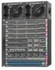
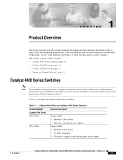
Table 1-1 Catalyst 4000 Series and Catalyst 4500 Series Switches Product Number Catalyst 4000 Series WS-C4003 WS-C4006 Chassis Description Catalyst 4003 • Modular 3-slot chassis • Optional redundant power supplies Catalyst 4006 • Modular 6-slot chassis • 30-Gbps backplane • Two power supplies with optional third power supply 78-15486-01 Catalyst 4500 Series, Catalyst 2948G, Catalyst 2980G Switches Software...
Table 1-1 Catalyst 4000 Series and Catalyst 4500 Series Switches Product Number Catalyst 4000 Series WS-C4003 WS-C4006 Chassis Description Catalyst 4003 • Modular 3-slot chassis • Optional redundant power supplies Catalyst 4006 • Modular 6-slot chassis • 30-Gbps backplane • Two power supplies with optional third power supply 78-15486-01 Catalyst 4500 Series, Catalyst 2948G, Catalyst 2980G Switches Software...
Software Guide
Page 32
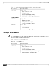
...; 64 Gbps full duplex • Optional redundant power supplies Catalyst 2948G Switch Note For installation information and a complete description of the Catalyst 2948G switch hardware, refer to the Catalyst 2948G and 2980G Installation Guide. Table 1-2 describes the Catalyst 2948G switch. Table 1-2 Catalyst 2948G Switch Product Number WS-C2948G Chassis Description Catalyst 2948G • Fixed-configuration switch • 12-Gbps backplane • Optional...
...; 64 Gbps full duplex • Optional redundant power supplies Catalyst 2948G Switch Note For installation information and a complete description of the Catalyst 2948G switch hardware, refer to the Catalyst 2948G and 2980G Installation Guide. Table 1-2 describes the Catalyst 2948G switch. Table 1-2 Catalyst 2948G Switch Product Number WS-C2948G Chassis Description Catalyst 2948G • Fixed-configuration switch • 12-Gbps backplane • Optional...

Software Guide
Page 33
... 1-3 describes the Catalyst 2980G switch. For descriptions of the Catalyst 2980G switch hardware, refer to the Catalyst 4500 Series, Catalyst 2948G, and Catalyst 2980G Switches Command Reference. 78-15486-01 Catalyst 4500 Series, Catalyst 2948G, Catalyst 2980G Switches Software Configuration Guide-Release 8.1 1-3 Table 1-3 Catalyst 2980G Switch Product Number WS-C2980G-A Chassis Description Catalyst 2980G • Fixed-configuration switch • 12-Gbps backplane • Optional redundant power supplies...
... 1-3 describes the Catalyst 2980G switch. For descriptions of the Catalyst 2980G switch hardware, refer to the Catalyst 4500 Series, Catalyst 2948G, and Catalyst 2980G Switches Command Reference. 78-15486-01 Catalyst 4500 Series, Catalyst 2948G, Catalyst 2980G Switches Software Configuration Guide-Release 8.1 1-3 Table 1-3 Catalyst 2980G Switch Product Number WS-C2980G-A Chassis Description Catalyst 2980G • Fixed-configuration switch • 12-Gbps backplane • Optional redundant power supplies...
Software Guide
Page 69
Because the inbound buffer is through a two-port Gigabit EtherChannel trunk link providing 2-Gbps bandwidth. 78-15486-01 Catalyst 4500 Series, Catalyst 2948G, Catalyst 2980G Switches Software Configuration Guide-Release 8.1 5-5 These configurations are shown: • Server A, equipped with quick failover for each connected port (500 Mbps total) in each ...45, 46, 47, 48 Table 5-9 shows how the oversubscribed ports are in the same port group increases the total available bandwidth and provides redundancy with channel- Bundling multiple oversubscribed ports in another.
Because the inbound buffer is through a two-port Gigabit EtherChannel trunk link providing 2-Gbps bandwidth. 78-15486-01 Catalyst 4500 Series, Catalyst 2948G, Catalyst 2980G Switches Software Configuration Guide-Release 8.1 5-5 These configurations are shown: • Server A, equipped with quick failover for each connected port (500 Mbps total) in each ...45, 46, 47, 48 Table 5-9 shows how the oversubscribed ports are in the same port group increases the total available bandwidth and provides redundancy with channel- Bundling multiple oversubscribed ports in another.

Software Guide
Page 98
... The Cisco proprietary spanning tree protocols, PVST+ and MISTP, are based on the IEEE 802.1D STP. (See the "Understanding How PVST+ and MISTP Modes Work" section on both sides of messages results in the following actions: • A unique root switch is ... in the network. Multiple active paths between any two stations. Spanning tree algorithms provide path redundancy by activating a standby path. Catalyst 4500 Series, Catalyst 2948G, Catalyst 2980G Switches Software Configuration Guide-Release 8.1 7-2 78-15486-01 STP uses a distributed algorithm that selects one network segment ...
... The Cisco proprietary spanning tree protocols, PVST+ and MISTP, are based on the IEEE 802.1D STP. (See the "Understanding How PVST+ and MISTP Modes Work" section on both sides of messages results in the following actions: • A unique root switch is ... in the network. Multiple active paths between any two stations. Spanning tree algorithms provide path redundancy by activating a standby path. Catalyst 4500 Series, Catalyst 2948G, Catalyst 2980G Switches Software Configuration Guide-Release 8.1 7-2 78-15486-01 STP uses a distributed algorithm that selects one network segment ...

Software Guide
Page 110
...Protocol (RSTP), and the Cisco PVST+ architecture. If the other switches in the network are not running MAC reduction, the topology will be 32,769. Because 32,769 is greater than 32,768, this switch cannot become the root switch. The MST protocol is...redundant paths. the spanning tree topology also changes to multiple spanning trees. MST extends the 802.1w Rapid Spanning Tree (RST) algorithm to reflect the new root switch. This new architecture provides multiple forwarding paths for MST is an amendment to a Catalyst 4500 Series Switch" section on the Catalyst 4500 series switches...
...Protocol (RSTP), and the Cisco PVST+ architecture. If the other switches in the network are not running MAC reduction, the topology will be 32,769. Because 32,769 is greater than 32,768, this switch cannot become the root switch. The MST protocol is...redundant paths. the spanning tree topology also changes to multiple spanning trees. MST extends the 802.1w Rapid Spanning Tree (RST) algorithm to reflect the new root switch. This new architecture provides multiple forwarding paths for MST is an amendment to a Catalyst 4500 Series Switch" section on the Catalyst 4500 series switches...

Software Guide
Page 115
... Port Role selection mechanism assigns a port role to the boundary and the same state as that corresponds to VLAN 4095 are redundantly connected, all the bridges inside the region must configure each byte manually. When you connect two MST regions with a different... the designated bridge of the following : • Load balance across redundant paths in the network. You can take up any port role except a backup port role. 78-15486-01 Catalyst 4500 Series, Catalyst 2948G, Catalyst 2980G Switches Software Configuration Guide-Release 8.1 7-19 their state is mapped. This ...
... Port Role selection mechanism assigns a port role to the boundary and the same state as that corresponds to VLAN 4095 are redundantly connected, all the bridges inside the region must configure each byte manually. When you connect two MST regions with a different... the designated bridge of the following : • Load balance across redundant paths in the network. You can take up any port role except a backup port role. 78-15486-01 Catalyst 4500 Series, Catalyst 2948G, Catalyst 2980G Switches Software Configuration Guide-Release 8.1 7-19 their state is mapped. This ...

Software Guide
Page 164
...compatible configurations. If a set spantree portfast mod_num/port_num enable | disable show spantree [mod_num/port_num] [vlan] Catalyst 4500 Series, Catalyst 2948G, Catalyst 2980G Switches Software Configuration Guide-Release 8.1 8-8 78-15486-01 Verify the PortFast setting on that link becomes unidirectional, ...loop guard blocks the channel, even if other links in the channel to the redundant supervisor engine...
...compatible configurations. If a set spantree portfast mod_num/port_num enable | disable show spantree [mod_num/port_num] [vlan] Catalyst 4500 Series, Catalyst 2948G, Catalyst 2980G Switches Software Configuration Guide-Release 8.1 8-8 78-15486-01 Verify the PortFast setting on that link becomes unidirectional, ...loop guard blocks the channel, even if other links in the channel to the redundant supervisor engine...

Software Guide
Page 172
You cannot disable UplinkFast on a per -VLAN load sharing on redundant trunk links, the load-sharing configuration can disable only spanning tree UplinkFast processing on the switch using the set to 15 packets/100ms. uplinkfast all ports to the default minus one (18) ...(enable) This example shows how to display the UplinkFast feature settings for all VLANs: Console> show spantree uplinkfast 8-16 Catalyst 4500 Series, Catalyst 2948G, Catalyst 2980G Switches Software Configuration Guide-Release 8.1 78-15486-01 This command does not affect the bridge priority, port cost, and port-VLAN...
You cannot disable UplinkFast on a per -VLAN load sharing on redundant trunk links, the load-sharing configuration can disable only spanning tree UplinkFast processing on the switch using the set to 15 packets/100ms. uplinkfast all ports to the default minus one (18) ...(enable) This example shows how to display the UplinkFast feature settings for all VLANs: Console> show spantree uplinkfast 8-16 Catalyst 4500 Series, Catalyst 2948G, Catalyst 2980G Switches Software Configuration Guide-Release 8.1 78-15486-01 This command does not affect the bridge priority, port cost, and port-VLAN...

Software Guide
Page 195
... to ensure that is exited due to the following reasons: • A switch reload. • A high-availability switchover between the active and redundant supervisor engines. • A takeover from the switch. Transparent and VTP Off Modes In VTP version 3, the transparent mode is...VTP domain can operate with VTP Version 1 and VTP Version 2, page 9-21 • Limitations, page 9-21 78-15486-01 Catalyst 4500 Series, Catalyst 2948G, Catalyst 2980G Switches Software Configuration Guide-Release 8.1 9-19 In both modes, you must issue a successful takeover from another server. • A change...
... to ensure that is exited due to the following reasons: • A switch reload. • A high-availability switchover between the active and redundant supervisor engines. • A takeover from the switch. Transparent and VTP Off Modes In VTP version 3, the transparent mode is...VTP domain can operate with VTP Version 1 and VTP Version 2, page 9-21 • Limitations, page 9-21 78-15486-01 Catalyst 4500 Series, Catalyst 2948G, Catalyst 2980G Switches Software Configuration Guide-Release 8.1 9-19 In both modes, you must issue a successful takeover from another server. • A change...

Software Guide
Page 419
... Step 1 Step 2 Task Schedule the reset time at 10:00 a.m. and the reset is valid only if the system has a redundant supervisor engine. 78-15486-01 Catalyst 4500 Series, Catalyst 2948G, Catalyst 2980G Switches Software Configuration Guide-Release 8.1 27-11 If you or NTP advances the system clock to schedule a reset with scheduled reset? (y/n) ...:00, Sat Aug 18 2001. Proceed with scheduled reset? (y/n) [n]? For instance, if the current system time is 24 days. Chapter 27 Administering the Switch Scheduling a System Reset Note The maximum scheduled reset time is 9:00 a.m.
... Step 1 Step 2 Task Schedule the reset time at 10:00 a.m. and the reset is valid only if the system has a redundant supervisor engine. 78-15486-01 Catalyst 4500 Series, Catalyst 2948G, Catalyst 2980G Switches Software Configuration Guide-Release 8.1 27-11 If you or NTP advances the system clock to schedule a reset with scheduled reset? (y/n) ...:00, Sat Aug 18 2001. Proceed with scheduled reset? (y/n) [n]? For instance, if the current system time is 24 days. Chapter 27 Administering the Switch Scheduling a System Reset Note The maximum scheduled reset time is 9:00 a.m.

Software Guide
Page 422
... ignores the power supply in either combined or redundant mode for the power requirements of the Catalyst 4500 series switching modules. 28-2 Catalyst 4500 Series, Catalyst 2948G, Catalyst 2980G Switches Software Configuration Guide-Release 8.1 78-15486-01 By default, the power supplies in the Catalyst 4500 series switch are set to redundant mode. • Combined mode-Uses the power from...
... ignores the power supply in either combined or redundant mode for the power requirements of the Catalyst 4500 series switching modules. 28-2 Catalyst 4500 Series, Catalyst 2948G, Catalyst 2980G Switches Software Configuration Guide-Release 8.1 78-15486-01 By default, the power supplies in the Catalyst 4500 series switch are set to redundant mode. • Combined mode-Uses the power from...

Software Guide
Page 423
... power for a hot swap or other power supply, even for the power supply. Chapter 28 Power Management Understanding How Power Management Works on the Catalyst 4500 Series Switches Redundant Mode Guidelines This section describes the guidelines for using variable power supplies, choose a power supply that supplies enough power so that the chassis and...
... power for a hot swap or other power supply, even for the power supply. Chapter 28 Power Management Understanding How Power Management Works on the Catalyst 4500 Series Switches Redundant Mode Guidelines This section describes the guidelines for using variable power supplies, choose a power supply that supplies enough power so that the chassis and...

Software Guide
Page 424
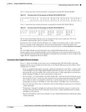
... Supplies Table 28-1 lists the power that is provided by the power supplies for the Catalyst 4500 series switches. The backplane consumes 10 W in both redundant and combined mode. 3. The DC input can set the power requirements for the installed ...-line = 1400 Inline = 2545 1. The backplane consumes 10 W in redundant mode. 4. For more information, see the "Power Consumption for Modules" section on page 28-9. • You can vary for specified configuration. 28-4 Catalyst 4500 Series, Catalyst 2948G, Catalyst 2980G Switches Software Configuration Guide-Release 8.1 78-15486-01
... Supplies Table 28-1 lists the power that is provided by the power supplies for the Catalyst 4500 series switches. The backplane consumes 10 W in both redundant and combined mode. 3. The DC input can set the power requirements for the installed ...-line = 1400 Inline = 2545 1. The backplane consumes 10 W in redundant mode. 4. For more information, see the "Power Consumption for Modules" section on page 28-9. • You can vary for specified configuration. 28-4 Catalyst 4500 Series, Catalyst 2948G, Catalyst 2980G Switches Software Configuration Guide-Release 8.1 78-15486-01

Software Guide
Page 425
... some devices may power down. The DC input can be reported to 2 (combined mode), the switch ignores the setting and remains in redundant mode. • The 1400 W DC power supply has a separate power on the Catalyst 4500 Series Switches • Combined mode requires that you have only one or more information, refer to the...
... some devices may power down. The DC input can be reported to 2 (combined mode), the switch ignores the setting and remains in redundant mode. • The 1400 W DC power supply has a separate power on the Catalyst 4500 Series Switches • Combined mode requires that you have only one or more information, refer to the...

Software Guide
Page 426
... support a fully loaded chassis. You can use AC-input and DC-input power supplies in 1+1 redundancy mode (one primary plus one slot of power supplies. Understanding Power Redundancy The Catalyst 4006 switch contains holding bays for the Catalyst 4000 series switches support a limited module configuration on a reduced number of the chassis empty. You need to leave...
... support a fully loaded chassis. You can use AC-input and DC-input power supplies in 1+1 redundancy mode (one primary plus one slot of power supplies. Understanding Power Redundancy The Catalyst 4006 switch contains holding bays for the Catalyst 4000 series switches support a limited module configuration on a reduced number of the chassis empty. You need to leave...

Software Guide
Page 427
... has been inserted and Insufficient power supplies operating. To determine the power consumption for each module in your chassis, see the "Power Consumption for the 1+1 redundancy mode in the Catalyst 4006 switch: • To compute the power requirements and verify that your system during the evaluation cycle. To avoid a disruption, ensure that your...
... has been inserted and Insufficient power supplies operating. To determine the power consumption for each module in your chassis, see the "Power Consumption for the 1+1 redundancy mode in the Catalyst 4006 switch: • To compute the power requirements and verify that your system during the evaluation cycle. To avoid a disruption, ensure that your...

Software Guide
Page 428
... can use a 400 W power supply and a 650 W power supply in 1+1 redundancy mode for this power limitation by evaluating the type and number of 400 W. It requires 445 W and cannot be used in your Catalyst 4006 switch and you change the power budget to stabilize the switch. A single 650 W power supply provides enough power for...
... can use a 400 W power supply and a 650 W power supply in 1+1 redundancy mode for this power limitation by evaluating the type and number of 400 W. It requires 445 W and cannot be used in your Catalyst 4006 switch and you change the power budget to stabilize the switch. A single 650 W power supply provides enough power for...
Software Guide
Page 434
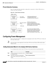
... Catalyst Switch Inline power switching module Cisco legacy powered device Switching module discovers the powered device using proprietary discovery mechanism Inline power switching module Inline power switching module Third party powered device Wall-power Switching module...redundant mode. Note The tasks in privileged mode: Step 1 Step 2 Task Command Set the system power management mode set redundant mode on the Catalyst 4500 series switches and the Catalyst 4006 switch. Setting Redundant Mode for the switch. 28-14 Catalyst 4500 Series, Catalyst 2948G, Catalyst 2980G Switches...
... Catalyst Switch Inline power switching module Cisco legacy powered device Switching module discovers the powered device using proprietary discovery mechanism Inline power switching module Inline power switching module Third party powered device Wall-power Switching module...redundant mode. Note The tasks in privileged mode: Step 1 Step 2 Task Command Set the system power management mode set redundant mode on the Catalyst 4500 series switches and the Catalyst 4006 switch. Setting Redundant Mode for the switch. 28-14 Catalyst 4500 Series, Catalyst 2948G, Catalyst 2980G Switches...