
Hardware Installation Guide
Page 9
... Port 3-11 Planning the Stack 3-12 Planning Considerations 3-12 Powering Considerations 3-13 Cabling Considerations 3-14 Recommended Cabling Configurations 3-15 Installing the Switch 3-17 Rack Mounting 3-18 Removing Screws from the Switch 3-19 Attaching Brackets to the Catalyst 3750G-24TS Switch 3-20 Attaching Brackets to the Catalyst 3750-24TS, 3750G-24T, 3750G-12S, and 3750-48TS Switches 3-25 Mounting the Switch in a Rack 3-28 Attaching...
... Port 3-11 Planning the Stack 3-12 Planning Considerations 3-12 Powering Considerations 3-13 Cabling Considerations 3-14 Recommended Cabling Configurations 3-15 Installing the Switch 3-17 Rack Mounting 3-18 Removing Screws from the Switch 3-19 Attaching Brackets to the Catalyst 3750G-24TS Switch 3-20 Attaching Brackets to the Catalyst 3750-24TS, 3750G-24T, 3750G-12S, and 3750-48TS Switches 3-25 Mounting the Switch in a Rack 3-28 Attaching...

Hardware Installation Guide
Page 10
... a Failed Stack Member 4-7 A A P P E N D I X Technical Specifications A-1 B A P P E N D I X Connector and Cable Specifications B-1 Connector Specifications B-1 10/100/1000 Ports B-1 Connecting to 1000BASE-T Devices B-2 10/100 Ports B-3 SFP Module Ports B-5 Console Port B-6 Cable and Adapter Specifications B-6 Two Twisted-Pair Cable Pinouts B-6 Four Twisted-Pair Cable Pinouts for 10/100 Ports B-7 Four Twisted-Pair Cable Pinouts for 1000BASE-T Ports B-8 Catalyst 3750 Switch Hardware Installation...
... a Failed Stack Member 4-7 A A P P E N D I X Technical Specifications A-1 B A P P E N D I X Connector and Cable Specifications B-1 Connector Specifications B-1 10/100/1000 Ports B-1 Connecting to 1000BASE-T Devices B-2 10/100 Ports B-3 SFP Module Ports B-5 Console Port B-6 Cable and Adapter Specifications B-6 Two Twisted-Pair Cable Pinouts B-6 Four Twisted-Pair Cable Pinouts for 10/100 Ports B-7 Four Twisted-Pair Cable Pinouts for 1000BASE-T Ports B-8 Catalyst 3750 Switch Hardware Installation...

Hardware Installation Guide
Page 11
... X D A P P E N D I X Crossover Cable and Adapter Pinouts B-9 Identifying a Crossover Cable B-9 Adapter Pinouts B-10 Managing the Switch by Using the Cluster Management Suite C-1 Connecting to an Ethernet Port C-2 Launching the Switch Home Page C-3 CMS Requirements C-5 Recommended Configuration for Web-Based ...Stacking the Switches (Optional) D-5 Connecting to the Console Port D-7 Starting the Terminal Emulation Software D-9 Connecting to a Power Source D-9 Entering the Initial Configuration Information D-10 IP Settings D-10 Completing the Setup Program D-11 78-15136-02 Catalyst 3750 Switch...
... X D A P P E N D I X Crossover Cable and Adapter Pinouts B-9 Identifying a Crossover Cable B-9 Adapter Pinouts B-10 Managing the Switch by Using the Cluster Management Suite C-1 Connecting to an Ethernet Port C-2 Launching the Switch Home Page C-3 CMS Requirements C-5 Recommended Configuration for Web-Based ...Stacking the Switches (Optional) D-5 Connecting to the Console Port D-7 Starting the Terminal Emulation Software D-9 Connecting to a Power Source D-9 Entering the Initial Configuration Information D-10 IP Settings D-10 Completing the Setup Program D-11 78-15136-02 Catalyst 3750 Switch...

Hardware Installation Guide
Page 12
...E N D I X INDEX Translated Safety Warnings E-1 Attaching the Cisco RPS (model PWR300-AC-RPS-N1) E-1 Attaching the Cisco RPS (model PWR675-AC-RPS-N1) E-2 Installation Warning E-4 Installation Instructions E-5 Jewelry Removal Warning E-6 Stacking the Chassis Warning E-8 Main Disconnecting Device E-10 Grounded Equipment Warning E-... E-19 Redundant Power Supply Connection Warning E-24 Switch Installation Warning E-25 Restricted Area E-27 Ethernet Cable Shielding in Offices E-28 Laser Beam Exposure E-30 Laser Radiation E-31 E-32 Catalyst 3750 Switch Hardware Installation Guide x 78-15136-02
...E N D I X INDEX Translated Safety Warnings E-1 Attaching the Cisco RPS (model PWR300-AC-RPS-N1) E-1 Attaching the Cisco RPS (model PWR675-AC-RPS-N1) E-2 Installation Warning E-4 Installation Instructions E-5 Jewelry Removal Warning E-6 Stacking the Chassis Warning E-8 Main Disconnecting Device E-10 Grounded Equipment Warning E-... E-19 Redundant Power Supply Connection Warning E-24 Switch Installation Warning E-25 Restricted Area E-27 Ethernet Cable Shielding in Offices E-28 Laser Beam Exposure E-30 Laser Radiation E-31 E-32 Catalyst 3750 Switch Hardware Installation Guide x 78-15136-02
Hardware Installation Guide
Page 30
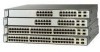
... in Figure 1-2, to connect the switch to configure it. Figure 1-1 Catalyst 3750 Switch and AC Power Cord 1 SYST RPS MASTR STAT 1X DUPLX SPEED STACK MODE 2X 11X 13X 12X 14X 23X Catalyst 3750 SERIES 24X 97175 2 1 Switch 2 AC power cord You also need to provide an Ethernet (Category 5) straight-through cable (not included), as a DHCP server...
... in Figure 1-2, to connect the switch to configure it. Figure 1-1 Catalyst 3750 Switch and AC Power Cord 1 SYST RPS MASTR STAT 1X DUPLX SPEED STACK MODE 2X 11X 13X 12X 14X 23X Catalyst 3750 SERIES 24X 97175 2 1 Switch 2 AC power cord You also need to provide an Ethernet (Category 5) straight-through cable (not included), as a DHCP server...

Hardware Installation Guide
Page 31
Figure 1-3 Connecting the Power 1 STACK 1 STACK 2 CONSOLE 1.2A-100R>06A-A2T4,IN05GV0-~60 HZ DSCPIENPCPO+IUWF1T2IEESvDRFISO@NUR1MP3RPAAELNYMUOATLE 97176 1 Switch 2 2 AC power cord 78-15136-02 Catalyst 3750 Switch Hardware Installation Guide 1-3 Chapter 1 Using Express Setup Figure 1-2 Ethernet Cable Powering On the Switch 89887 Powering On the Switch Complete these steps to power on the switch: Step 1 Connect one end of the AC power cord to the power connector on the switch rear panel, as shown in Figure 1-3.
Figure 1-3 Connecting the Power 1 STACK 1 STACK 2 CONSOLE 1.2A-100R>06A-A2T4,IN05GV0-~60 HZ DSCPIENPCPO+IUWF1T2IEESvDRFISO@NUR1MP3RPAAELNYMUOATLE 97176 1 Switch 2 2 AC power cord 78-15136-02 Catalyst 3750 Switch Hardware Installation Guide 1-3 Chapter 1 Using Express Setup Figure 1-2 Ethernet Cable Powering On the Switch 89887 Powering On the Switch Complete these steps to power on the switch: Step 1 Connect one end of the AC power cord to the power connector on the switch rear panel, as shown in Figure 1-3.

Hardware Installation Guide
Page 32
...-test (POST), a series of the power cable to a grounded AC outlet. The MASTR LED is a browser-based program that you plan to the switch after Express Startup is complete, only the SYST and STAT LEDs remain green. Catalyst 3750 Switch Hardware Installation Guide 1-4 78-15136-02 You...also required if you can connect to local routers and the Internet. POST lasts approximately 1 minute. After the switch powers on, it begins the power-on a stack master switch. Starting Express Setup Chapter 1 Using Express Setup Step 2 Connect the other end of tests that run automatically...
...-test (POST), a series of the power cable to a grounded AC outlet. The MASTR LED is a browser-based program that you plan to the switch after Express Startup is complete, only the SYST and STAT LEDs remain green. Catalyst 3750 Switch Hardware Installation Guide 1-4 78-15136-02 You...also required if you can connect to local routers and the Internet. POST lasts approximately 1 minute. After the switch powers on, it begins the power-on a stack master switch. Starting Express Setup Chapter 1 Using Express Setup Step 2 Connect the other end of tests that run automatically...

Hardware Installation Guide
Page 33
...until the four LEDs above the Mode button turn green. Note If all of the switch, as shown in Figure 1-5. 78-15136-02 Catalyst 3750 Switch Hardware Installation Guide 1-5 Step 4 Connect the Ethernet cable (not included) to a 10/100 Ethernet port or small form-factor pluggable (SFP.... For more information, see the "Clearing the Switch IP Address and Configuration" section on the front panel of the LEDs begin to the switch. This takes approximately 3 seconds. Figure 1-4 Starting Express Setup SYST RPS MASTR STAT DUPLX SPEED STACK MODE 97173 1 1 Mode button Step 3 Release...
...until the four LEDs above the Mode button turn green. Note If all of the switch, as shown in Figure 1-5. 78-15136-02 Catalyst 3750 Switch Hardware Installation Guide 1-5 Step 4 Connect the Ethernet cable (not included) to a 10/100 Ethernet port or small form-factor pluggable (SFP.... For more information, see the "Clearing the Switch IP Address and Configuration" section on the front panel of the LEDs begin to the switch. This takes approximately 3 seconds. Figure 1-4 Starting Express Setup SYST RPS MASTR STAT DUPLX SPEED STACK MODE 97173 1 1 Mode button Step 3 Release...

Hardware Installation Guide
Page 34
...10.0.0.1, as shown in Figure 1-6, and press Enter. Catalyst 3750 Switch Hardware Installation Guide 1-6 78-15136-02 Figure 1-5 Connecting the Switch and PC or Workstation Ethernet Ports 1 SYST RPS MASTR STAT 1X DUPLX SPEED STACK MODE 2X 11X 13X 12X 14X 23X Catalyst 3750 SERIES 24X 2 97174 3 1 Switch 2 Ethernet cable 3 PC or workstation Step 5 Step 6 Step ... the port status LEDs on both connected Ethernet ports are green. Starting Express Setup Chapter 1 Using Express Setup Caution Do not connect the switch to any device other end of the cable to configure it.
...10.0.0.1, as shown in Figure 1-6, and press Enter. Catalyst 3750 Switch Hardware Installation Guide 1-6 78-15136-02 Figure 1-5 Connecting the Switch and PC or Workstation Ethernet Ports 1 SYST RPS MASTR STAT 1X DUPLX SPEED STACK MODE 2X 11X 13X 12X 14X 23X Catalyst 3750 SERIES 24X 2 97174 3 1 Switch 2 Ethernet cable 3 PC or workstation Step 5 Step 6 Step ... the port status LEDs on both connected Ethernet ports are green. Starting Express Setup Chapter 1 Using Express Setup Caution Do not connect the switch to any device other end of the cable to configure it.

Hardware Installation Guide
Page 42
...- 1000BASE-LX - 1000BASE-T Note When installed in Catalyst 3750 switches, 1000BASE-T small form-factor pluggable (SFP) modules can stack up to the Catalyst 3750-24TS, 3750G-24T, 3750-48TS, and 3750G-12S switches. Connection for optional Cisco RPS 300 redundant power system that operates on AC ...duplex mode or in a stack by cabling the StackWise ports. These are hot-swappable • Power redundancy - For 10/100/1000 ports, autonegotiates the speed and supports only full-duplex mode • The Catalyst 3750 switches support stacking. Catalyst 3750-48TS-48 10/100 Ethernet ports ...
...- 1000BASE-LX - 1000BASE-T Note When installed in Catalyst 3750 switches, 1000BASE-T small form-factor pluggable (SFP) modules can stack up to the Catalyst 3750-24TS, 3750G-24T, 3750-48TS, and 3750G-12S switches. Connection for optional Cisco RPS 300 redundant power system that operates on AC ...duplex mode or in a stack by cabling the StackWise ports. These are hot-swappable • Power redundancy - For 10/100/1000 ports, autonegotiates the speed and supports only full-duplex mode • The Catalyst 3750 switches support stacking. Catalyst 3750-48TS-48 10/100 Ethernet ports ...

Hardware Installation Guide
Page 55
... 2-9 Catalyst 3750G-24TS Rear Panel Rear Panel Description 86547 STACK 1 STACK 2 CONSOLE DSCPIENPCPO+IUWF1TI2EESvDRFISO@NUR1MP7RPAaELNYMUOATLE 1 23 4 5 1 StackWise ports 2 RJ-45 console port 3 Fan exhaust 4 AC power connector 5 RPS connector StackWise Ports The Catalyst 3750 switch ships with a 0.5-meter StackWise cable (72-2632-XX CABASY) that you can order these StackWise cables from your Cisco sales representative: • CAB-STACK-50CM...
... 2-9 Catalyst 3750G-24TS Rear Panel Rear Panel Description 86547 STACK 1 STACK 2 CONSOLE DSCPIENPCPO+IUWF1TI2EESvDRFISO@NUR1MP7RPAaELNYMUOATLE 1 23 4 5 1 StackWise ports 2 RJ-45 console port 3 Fan exhaust 4 AC power connector 5 RPS connector StackWise Ports The Catalyst 3750 switch ships with a 0.5-meter StackWise cable (72-2632-XX CABASY) that you can order these StackWise cables from your Cisco sales representative: • CAB-STACK-50CM...

Hardware Installation Guide
Page 61
...-15136-02 Catalyst 3750 Switch Hardware Installation Guide 3-1 Read the topics and perform the procedures in mind while planning your switch and how to keep in this order: • Preparing for Installation, page 3-1 • Verifying Switch Operation, page 3-8 • Planning the Stack, page 3-12 • Installing the Switch, page 3-17 • Connecting StackWise Cable to StackWise Ports...
...-15136-02 Catalyst 3750 Switch Hardware Installation Guide 3-1 Read the topics and perform the procedures in mind while planning your switch and how to keep in this order: • Preparing for Installation, page 3-1 • Verifying Switch Operation, page 3-8 • Planning the Stack, page 3-12 • Installing the Switch, page 3-17 • Connecting StackWise Cable to StackWise Ports...
Hardware Installation Guide
Page 67
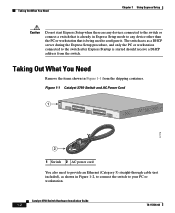
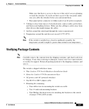
... AC power cord (AC-powered switches) • One RJ-45-to the switch (Catalyst 3750G-24TS switch) 78-15136-02 Catalyst 3750 Switch Hardware Installation Guide 3-7 If you rack mount them. - Return all packing material to the rear panel, make sure you cable the switches before you do not have access...and save it might damage the cables. • Airflow around the switch and through the vents is unrestricted. • Temperature around it . Note If the switch is access to stack the switches. Two 19-inch rack-mounting brackets - Make sure the cabling is safely away from the ...
... AC power cord (AC-powered switches) • One RJ-45-to the switch (Catalyst 3750G-24TS switch) 78-15136-02 Catalyst 3750 Switch Hardware Installation Guide 3-7 If you rack mount them. - Return all packing material to the rear panel, make sure you cable the switches before you do not have access...and save it might damage the cables. • Airflow around the switch and through the vents is unrestricted. • Temperature around it . Note If the switch is access to stack the switches. Two 19-inch rack-mounting brackets - Make sure the cabling is safely away from the ...

Hardware Installation Guide
Page 71
...Stack LEDs turn green for 2 seconds. Other LEDs are green. The RPS LED turns either solid amber or blinking amber. If you are installing the Catalyst 3750-24TS, 3750G-24T, 3750G-24T, 3750G-12S, or 3750-48TS switches, you can use the Cisco RPS 300. If a switch fails POST, the System LED turns amber. Disconnect the cable from the switch.... Warning Attach only the Cisco RPS 675...
...Stack LEDs turn green for 2 seconds. Other LEDs are green. The RPS LED turns either solid amber or blinking amber. If you are installing the Catalyst 3750-24TS, 3750G-24T, 3750G-24T, 3750G-12S, or 3750-48TS switches, you can use the Cisco RPS 300. If a switch fails POST, the System LED turns amber. Disconnect the cable from the switch.... Warning Attach only the Cisco RPS 675...

Hardware Installation Guide
Page 72
...-48TS switches are the same depth, and the Catalyst 3750G-12S and 3750G-24T switches are planning to stack the switches. If you require the 1-meter cable or 3-meter cable, you can order it easier to cable the switches. • Length of the rack if you are deeper than the other switches. Planning the Stack Chapter 3 Switch Installation Planning the Stack If you plan to stack your Cisco...
...-48TS switches are the same depth, and the Catalyst 3750G-12S and 3750G-24T switches are planning to stack the switches. If you require the 1-meter cable or 3-meter cable, you can order it easier to cable the switches. • Length of the rack if you are deeper than the other switches. Planning the Stack Chapter 3 Switch Installation Planning the Stack If you plan to stack your Cisco...

Hardware Installation Guide
Page 74
therefore, this stack partitions into two stacks with switch 1 and switch 3 being stack masters. 3-14 Catalyst 3750 Switch Hardware Installation Guide 78-15136-02 Figure 3-2 Example of a Stack with Full Bandwidth Connections 86821 A B C Figure 3-3 shows an example of a stack of Catalyst 3750 switches with failover conditions. Figure 3-3 Example of Catalyst 3750 switches with incomplete StackWise cabling connections. This stack provides only half bandwidth and does not...
therefore, this stack partitions into two stacks with switch 1 and switch 3 being stack masters. 3-14 Catalyst 3750 Switch Hardware Installation Guide 78-15136-02 Figure 3-2 Example of a Stack with Full Bandwidth Connections 86821 A B C Figure 3-3 shows an example of a stack of Catalyst 3750 switches with failover conditions. Figure 3-3 Example of Catalyst 3750 switches with incomplete StackWise cabling connections. This stack provides only half bandwidth and does not...

Hardware Installation Guide
Page 75
... cable. In this example, the switches are stacked in Vertical Racks or on a table. This configuration provides redundant connections. 78-15136-02 Catalyst 3750 Switch Hardware Installation Guide 3-15 Stacking Switches in a vertical rack or on a Table Figure 3-6 is an example of a Partitioned Stack with a Failover Condition A B 86824 Recommended Cabling Configurations This section describes the recommended cabling configurations for stacking the switches...
... cable. In this example, the switches are stacked in Vertical Racks or on a table. This configuration provides redundant connections. 78-15136-02 Catalyst 3750 Switch Hardware Installation Guide 3-15 Stacking Switches in a vertical rack or on a Table Figure 3-6 is an example of a Partitioned Stack with a Failover Condition A B 86824 Recommended Cabling Configurations This section describes the recommended cabling configurations for stacking the switches...

Hardware Installation Guide
Page 76
This configuration also provides redundant connections. Planning the Stack Chapter 3 Switch Installation Figure 3-6 Stacking the Switches in addition to the supplied 0.5-meter StackWise cable. Figure 3-7 Stacking the Catalyst 3750 Switches in a Vertical Rack or on a Table Using the 0.5-meter StackWise Cable 86586 The configuration examples in Figure 3-7 use the 3-meter StackWise cable in a Vertical Rack or on a Table Using 0.5-meter and 3-meter StackWise Cables 86585 3-16 Catalyst 3750 Switch Hardware Installation Guide 78-15136-02
This configuration also provides redundant connections. Planning the Stack Chapter 3 Switch Installation Figure 3-6 Stacking the Switches in addition to the supplied 0.5-meter StackWise cable. Figure 3-7 Stacking the Catalyst 3750 Switches in a Vertical Rack or on a Table Using the 0.5-meter StackWise Cable 86586 The configuration examples in Figure 3-7 use the 3-meter StackWise cable in a Vertical Rack or on a Table Using 0.5-meter and 3-meter StackWise Cables 86585 3-16 Catalyst 3750 Switch Hardware Installation Guide 78-15136-02

Hardware Installation Guide
Page 77
..., page 3-32 • Table or Shelf Mounting, page 3-36 78-15136-02 Catalyst 3750 Switch Hardware Installation Guide 3-17 Figure 3-8 Stacking up to connect the switches. Use the 1-meter and 3-meter StackWise cables to Eight Switches in a Side-by-Side Mounting Configuration 86825 Figure 3-9 Stacking Nine Switches in a Side-by -Side Mounting in a Rack or on a Wall Figure...
..., page 3-32 • Table or Shelf Mounting, page 3-36 78-15136-02 Catalyst 3750 Switch Hardware Installation Guide 3-17 Figure 3-8 Stacking up to connect the switches. Use the 1-meter and 3-meter StackWise cables to Eight Switches in a Side-by-Side Mounting Configuration 86825 Figure 3-9 Stacking Nine Switches in a Side-by -Side Mounting in a Rack or on a Wall Figure...

Hardware Installation Guide
Page 196
...2-7 fiber-optic cabling guidelines 3-6 installation 3-41 to 3-43 shelf-mounting 3-36 Simple Network Management Protocol See SNMP SNMP network management platforms 2-18 software switch management 2-18 specifications A-1 stacking cabling considerations 3-14 connecting...switch installation warning E-25 switch powering on 3-10 system LED 2-9 T table-mounting 3-36 technical specifications A-1 telco racks 3-18 Telnet, and accessing the CLI 2-18 temperature, operating A-1 terminal, connecting to switch 3-9 terminal emulation software 3-8, D-9 translated warnings E-1 to E-31 IN-6 Catalyst 3750 Switch...
...2-7 fiber-optic cabling guidelines 3-6 installation 3-41 to 3-43 shelf-mounting 3-36 Simple Network Management Protocol See SNMP SNMP network management platforms 2-18 software switch management 2-18 specifications A-1 stacking cabling considerations 3-14 connecting...switch installation warning E-25 switch powering on 3-10 system LED 2-9 T table-mounting 3-36 technical specifications A-1 telco racks 3-18 Telnet, and accessing the CLI 2-18 temperature, operating A-1 terminal, connecting to switch 3-9 terminal emulation software 3-8, D-9 translated warnings E-1 to E-31 IN-6 Catalyst 3750 Switch...

