
Hardware Installation Guide
Page 9
... Considerations 3-12 Powering Considerations 3-13 Cabling Considerations 3-14 Recommended Cabling Configurations 3-15 Installing the Switch 3-17 Rack Mounting 3-18 Removing Screws from the Switch 3-19 Attaching Brackets to the Catalyst 3750G-24TS Switch 3-20 Attaching Brackets to the Catalyst 3750-24TS, 3750G-24T, 3750G-12S, and 3750-48TS Switches 3-25 Mounting the Switch in a Rack 3-28 Attaching the Cable Guide 3-30 Wall Mounting 3-32...
... Considerations 3-12 Powering Considerations 3-13 Cabling Considerations 3-14 Recommended Cabling Configurations 3-15 Installing the Switch 3-17 Rack Mounting 3-18 Removing Screws from the Switch 3-19 Attaching Brackets to the Catalyst 3750G-24TS Switch 3-20 Attaching Brackets to the Catalyst 3750-24TS, 3750G-24T, 3750G-12S, and 3750-48TS Switches 3-25 Mounting the Switch in a Rack 3-28 Attaching the Cable Guide 3-30 Wall Mounting 3-32...

Hardware Installation Guide
Page 10
... 4-7 A A P P E N D I X Technical Specifications A-1 B A P P E N D I X Connector and Cable Specifications B-1 Connector Specifications B-1 10/100/1000 Ports B-1 Connecting to 1000BASE-T Devices B-2 10/100 Ports B-3 SFP Module Ports B-5 Console Port B-6 Cable and Adapter Specifications B-6 Two Twisted-Pair Cable Pinouts B-6 Four Twisted-Pair Cable Pinouts for 10/100 Ports B-7 Four Twisted-Pair Cable Pinouts for 1000BASE-T Ports B-8 Catalyst 3750 Switch Hardware Installation Guide viii...
... 4-7 A A P P E N D I X Technical Specifications A-1 B A P P E N D I X Connector and Cable Specifications B-1 Connector Specifications B-1 10/100/1000 Ports B-1 Connecting to 1000BASE-T Devices B-2 10/100 Ports B-3 SFP Module Ports B-5 Console Port B-6 Cable and Adapter Specifications B-6 Two Twisted-Pair Cable Pinouts B-6 Four Twisted-Pair Cable Pinouts for 10/100 Ports B-7 Four Twisted-Pair Cable Pinouts for 1000BASE-T Ports B-8 Catalyst 3750 Switch Hardware Installation Guide viii...

Hardware Installation Guide
Page 11
...D I X D A P P E N D I X Crossover Cable and Adapter Pinouts B-9 Identifying a Crossover Cable B-9 Adapter Pinouts B-10 Managing the Switch by Using the Cluster Management Suite C-1 Connecting to an Ethernet Port C-2 Launching the Switch Home Page C-3 CMS Requirements C-5 Recommended Configuration for Web-Based Management ...Switches (Optional) D-5 Connecting to the Console Port D-7 Starting the Terminal Emulation Software D-9 Connecting to a Power Source D-9 Entering the Initial Configuration Information D-10 IP Settings D-10 Completing the Setup Program D-11 78-15136-02 Catalyst 3750 Switch...
...D I X D A P P E N D I X Crossover Cable and Adapter Pinouts B-9 Identifying a Crossover Cable B-9 Adapter Pinouts B-10 Managing the Switch by Using the Cluster Management Suite C-1 Connecting to an Ethernet Port C-2 Launching the Switch Home Page C-3 CMS Requirements C-5 Recommended Configuration for Web-Based Management ...Switches (Optional) D-5 Connecting to the Console Port D-7 Starting the Terminal Emulation Software D-9 Connecting to a Power Source D-9 Entering the Initial Configuration Information D-10 IP Settings D-10 Completing the Setup Program D-11 78-15136-02 Catalyst 3750 Switch...

Hardware Installation Guide
Page 12
Contents E A P P E N D I X INDEX Translated Safety Warnings E-1 Attaching the Cisco RPS (model PWR300-AC-RPS-N1) E-1 Attaching the Cisco RPS (model PWR675-AC-RPS-N1) E-2 Installation Warning E-4 Installation Instructions E-5 Jewelry Removal Warning E-6 Stacking the Chassis Warning ... E-17 Chassis Warning for Rack-Mounting and Servicing E-19 Redundant Power Supply Connection Warning E-24 Switch Installation Warning E-25 Restricted Area E-27 Ethernet Cable Shielding in Offices E-28 Laser Beam Exposure E-30 Laser Radiation E-31 E-32 Catalyst 3750 Switch Hardware Installation Guide x 78-15136-02
Contents E A P P E N D I X INDEX Translated Safety Warnings E-1 Attaching the Cisco RPS (model PWR300-AC-RPS-N1) E-1 Attaching the Cisco RPS (model PWR675-AC-RPS-N1) E-2 Installation Warning E-4 Installation Instructions E-5 Jewelry Removal Warning E-6 Stacking the Chassis Warning ... E-17 Chassis Warning for Rack-Mounting and Servicing E-19 Redundant Power Supply Connection Warning E-24 Switch Installation Warning E-25 Restricted Area E-27 Ethernet Cable Shielding in Offices E-28 Laser Beam Exposure E-30 Laser Radiation E-31 E-32 Catalyst 3750 Switch Hardware Installation Guide x 78-15136-02
Hardware Installation Guide
Page 30
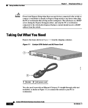
... Power Cord 1 SYST RPS MASTR STAT 1X DUPLX SPEED STACK MODE 2X 11X 13X 12X 14X 23X Catalyst 3750 SERIES 24X 97175 2 1 Switch 2 AC power cord You also need to provide an Ethernet (Category 5) straight-through cable (not included), as a DHCP server during the Express Setup procedure, and only the PC or workstation...
... Power Cord 1 SYST RPS MASTR STAT 1X DUPLX SPEED STACK MODE 2X 11X 13X 12X 14X 23X Catalyst 3750 SERIES 24X 97175 2 1 Switch 2 AC power cord You also need to provide an Ethernet (Category 5) straight-through cable (not included), as a DHCP server during the Express Setup procedure, and only the PC or workstation...

Hardware Installation Guide
Page 31
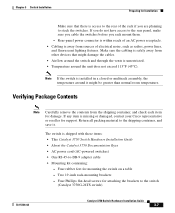
Figure 1-3 Connecting the Power 1 STACK 1 STACK 2 CONSOLE 1.2A-100R>06A-A2T4,IN05GV0-~60 HZ DSCPIENPCPO+IUWF1T2IEESvDRFISO@NUR1MP3RPAAELNYMUOATLE 97176 1 Switch 2 2 AC power cord 78-15136-02 Catalyst 3750 Switch Hardware Installation Guide 1-3 Chapter 1 Using Express Setup Figure 1-2 Ethernet Cable Powering On the Switch 89887 Powering On the Switch Complete these steps to power on the switch: Step 1 Connect one end of the AC power cord to the power connector on the switch rear panel, as shown in Figure 1-3.
Figure 1-3 Connecting the Power 1 STACK 1 STACK 2 CONSOLE 1.2A-100R>06A-A2T4,IN05GV0-~60 HZ DSCPIENPCPO+IUWF1T2IEESvDRFISO@NUR1MP3RPAAELNYMUOATLE 97176 1 Switch 2 2 AC power cord 78-15136-02 Catalyst 3750 Switch Hardware Installation Guide 1-3 Chapter 1 Using Express Setup Figure 1-2 Ethernet Cable Powering On the Switch 89887 Powering On the Switch Complete these steps to power on the switch: Step 1 Connect one end of the AC power cord to the power connector on the switch rear panel, as shown in Figure 1-3.

Hardware Installation Guide
Page 32
... Setup procedure, and only the PC or workstation connected to the switch. Note Before starting Express Setup, verify that the switch has passed POST and that the switch functions properly. Catalyst 3750 Switch Hardware Installation Guide 1-4 78-15136-02 When POST is started should...(CLI). For information about troubleshooting a POST failure, see Chapter 4, "Troubleshooting," to determine a course of the power cable to set up and configure the switch. Starting Express Setup Chapter 1 Using Express Setup Step 2 Connect the other end of action. POST lasts approximately 1...
... Setup procedure, and only the PC or workstation connected to the switch. Note Before starting Express Setup, verify that the switch has passed POST and that the switch functions properly. Catalyst 3750 Switch Hardware Installation Guide 1-4 78-15136-02 When POST is started should...(CLI). For information about troubleshooting a POST failure, see Chapter 4, "Troubleshooting," to determine a course of the power cable to set up and configure the switch. Starting Express Setup Chapter 1 Using Express Setup Step 2 Connect the other end of action. POST lasts approximately 1...

Hardware Installation Guide
Page 33
... it. Figure 1-4 Starting Express Setup SYST RPS MASTR STAT DUPLX SPEED STACK MODE 97173 1 1 Mode button Step 3 Release the Mode button. Step 4 Connect the Ethernet cable (not included) to the switch. Chapter 1 Using Express Setup Starting Express Setup Follow these steps to start the Express Setup program: Step 1 Step 2 Verify that the... 4-2. Press and hold the Mode button, as shown in Figure 1-4, until the four LEDs above the Mode button turn green. Note If all of the switch, as shown in Figure 1-5. 78-15136-02 Catalyst 3750 Switch Hardware Installation Guide 1-5
... it. Figure 1-4 Starting Express Setup SYST RPS MASTR STAT DUPLX SPEED STACK MODE 97173 1 1 Mode button Step 3 Release the Mode button. Step 4 Connect the Ethernet cable (not included) to the switch. Chapter 1 Using Express Setup Starting Express Setup Follow these steps to start the Express Setup program: Step 1 Step 2 Verify that the... 4-2. Press and hold the Mode button, as shown in Figure 1-4, until the four LEDs above the Mode button turn green. Note If all of the switch, as shown in Figure 1-5. 78-15136-02 Catalyst 3750 Switch Hardware Installation Guide 1-5

Hardware Installation Guide
Page 34
...Express Setup Caution Do not connect the switch to any device other end of the cable to configure it. Verify that the port status LEDs on your PC or workstation. Catalyst 3750 Switch Hardware Installation Guide 1-6 78-15136-02 Figure 1-5 Connecting the Switch and PC or Workstation Ethernet Ports 1... SYST RPS MASTR STAT 1X DUPLX SPEED STACK MODE 2X 11X 13X 12X 14X 23X Catalyst 3750 SERIES 24X 2 97174 3 1 Switch 2 Ethernet cable 3 PC or workstation Step 5 Step 6 Step 7 Connect the other than the PC or workstation being used to the...
...Express Setup Caution Do not connect the switch to any device other end of the cable to configure it. Verify that the port status LEDs on your PC or workstation. Catalyst 3750 Switch Hardware Installation Guide 1-6 78-15136-02 Figure 1-5 Connecting the Switch and PC or Workstation Ethernet Ports 1... SYST RPS MASTR STAT 1X DUPLX SPEED STACK MODE 2X 11X 13X 12X 14X 23X Catalyst 3750 SERIES 24X 2 97174 3 1 Switch 2 Ethernet cable 3 PC or workstation Step 5 Step 6 Step 7 Connect the other than the PC or workstation being used to the...

Hardware Installation Guide
Page 36
...by default. If not, reconnect the cable to the switch software configuration guide or the switch command reference. If not, make sure that POST successfully ran before starting Express Setup? Catalyst 3750 Switch Hardware Installation Guide 1-8 78-15136-02 To configure the switch by using the command-line interface ...or workstation, as shown Figure 1-5. Note The rest of this feature, refer to the Ethernet port on the switch and PC or workstation. Note On switches running Cisco IOS Release 12.1(14)EA1 or later, you can use the mdix auto command in the browser. •...
...by default. If not, reconnect the cable to the switch software configuration guide or the switch command reference. If not, make sure that POST successfully ran before starting Express Setup? Catalyst 3750 Switch Hardware Installation Guide 1-8 78-15136-02 To configure the switch by using the command-line interface ...or workstation, as shown Figure 1-5. Note The rest of this feature, refer to the Ethernet port on the switch and PC or workstation. Note On switches running Cisco IOS Release 12.1(14)EA1 or later, you can use the mdix auto command in the browser. •...

Hardware Installation Guide
Page 42
...-LX - 1000BASE-T Note When installed in Catalyst 3750 switches, 1000BASE-T small form-factor pluggable (SFP) modules can stack up to the Catalyst 3750-24TS, 3750G-24T, 3750-48TS, and 3750G-12S switches. Connection for optional Cisco RPS 300 redundant power system that operates on...cabling the StackWise ports. Catalyst 3750-48TS-48 10/100 Ethernet ports and 4 SFP module slots - For 10/100/1000 ports, autonegotiates the speed and supports only full-duplex mode • The Catalyst 3750 switches support stacking. These are hot-swappable • Power redundancy - Catalyst 3750 Switch...
...-LX - 1000BASE-T Note When installed in Catalyst 3750 switches, 1000BASE-T small form-factor pluggable (SFP) modules can stack up to the Catalyst 3750-24TS, 3750G-24T, 3750-48TS, and 3750G-12S switches. Connection for optional Cisco RPS 300 redundant power system that operates on...cabling the StackWise ports. Catalyst 3750-48TS-48 10/100 Ethernet ports and 4 SFP module slots - For 10/100/1000 ports, autonegotiates the speed and supports only full-duplex mode • The Catalyst 3750 switches support stacking. These are hot-swappable • Power redundancy - Catalyst 3750 Switch...

Hardware Installation Guide
Page 46
...cable for connections to a copper 10/100 or 10/100/1000 port on the switch, regardless the type of device on the switch to operate in any combination of half duplex, full duplex, 10 Mbps or 100 Mbps. Catalyst 3750 Switch Hardware Installation Guide 2-6 78-15136-02 When connecting the switch to workstations, servers, routers, and Cisco... the attached device supports it) and configures itself accordingly. Note On switches running Cisco IOS Release 12.1(14)EA1 or later, you can use a crossover cable. The automatic crossover feature is autonegotiate.) When set for 1000BASE-T connections...
...cable for connections to a copper 10/100 or 10/100/1000 port on the switch, regardless the type of device on the switch to operate in any combination of half duplex, full duplex, 10 Mbps or 100 Mbps. Catalyst 3750 Switch Hardware Installation Guide 2-6 78-15136-02 When connecting the switch to workstations, servers, routers, and Cisco... the attached device supports it) and configures itself accordingly. Note On switches running Cisco IOS Release 12.1(14)EA1 or later, you can use a crossover cable. The automatic crossover feature is autonegotiate.) When set for 1000BASE-T connections...

Hardware Installation Guide
Page 47
..., providing the uplink interfaces when inserted in the Catalyst 3750 release notes. You use fiber-optic cables with RJ-45 connectors to connect to a fiber-optic SFP module. You use the SFP modules for Gigabit uplink connections to other switches. The Catalyst 3750 models support these Cisco SFP options: • 1000BASE-LX • 1000BASE-SX...
..., providing the uplink interfaces when inserted in the Catalyst 3750 release notes. You use fiber-optic cables with RJ-45 connectors to connect to a fiber-optic SFP module. You use the SFP modules for Gigabit uplink connections to other switches. The Catalyst 3750 models support these Cisco SFP options: • 1000BASE-LX • 1000BASE-SX...

Hardware Installation Guide
Page 55
... damaged if connected to similar Cisco equipment. Chapter 2 Product Overview Figure 2-9 Catalyst 3750G-24TS Rear Panel Rear Panel Description 86547 STACK 1 STACK 2 CONSOLE DSCPIENPCPO+IUWF1TI2EESvDRFISO@NUR1MP7RPAaELNYMUOATLE 1 23 4 5 1 StackWise ports 2 RJ-45 console port 3 Fan exhaust 4 AC power connector 5 RPS connector StackWise Ports The Catalyst 3750 switch ships with a 0.5-meter StackWise cable (72-2632-XX CABASY) that...
... damaged if connected to similar Cisco equipment. Chapter 2 Product Overview Figure 2-9 Catalyst 3750G-24TS Rear Panel Rear Panel Description 86547 STACK 1 STACK 2 CONSOLE DSCPIENPCPO+IUWF1TI2EESvDRFISO@NUR1MP7RPAaELNYMUOATLE 1 23 4 5 1 StackWise ports 2 RJ-45 console port 3 Fan exhaust 4 AC power connector 5 RPS connector StackWise Ports The Catalyst 3750 switch ships with a 0.5-meter StackWise cable (72-2632-XX CABASY) that...

Hardware Installation Guide
Page 56
... internal power supply. Cisco RPS Connector Specific Cisco RPS modes support specific Catalyst 3750 switches: • Cisco RPS 300 (model PWR300-AC-RPS-N1) supports the Catalyst 3750-24TS, 3750G-24T, 3750G-12S, and 3750-48TS switches. • Cisco RPS 675 (model PWR675-AC-RPS-N1=) supports the Catalyst 3750 family of 300W. Use the supplied RPS connector cable to connect the RPS...
... internal power supply. Cisco RPS Connector Specific Cisco RPS modes support specific Catalyst 3750 switches: • Cisco RPS 300 (model PWR300-AC-RPS-N1) supports the Catalyst 3750-24TS, 3750G-24T, 3750G-12S, and 3750-48TS switches. • Cisco RPS 675 (model PWR675-AC-RPS-N1=) supports the Catalyst 3750 family of 300W. Use the supplied RPS connector cable to connect the RPS...

Hardware Installation Guide
Page 57
...the supplied RPS connector cable to connect the RPS to -DB-25 female DTE adapter. You can connect the switch to a PC by means of the console port and the supplied RJ-45-to the RPS receptacle. Chapter 2 Product Overview Rear Panel Description Cisco RPS 675 The ...-DSBUASYN=) containing that adapter from Cisco. For console port and adapter pinout information, see the "Connector and Cable Specifications" section on the Cisco RPS 300, refer to one failed device at a time. For more information on page B-1. 78-15136-02 Catalyst 3750 Switch Hardware Installation Guide 2-17 It ...
...the supplied RPS connector cable to connect the RPS to -DB-25 female DTE adapter. You can connect the switch to a PC by means of the console port and the supplied RJ-45-to the RPS receptacle. Chapter 2 Product Overview Rear Panel Description Cisco RPS 675 The ...-DSBUASYN=) containing that adapter from Cisco. For console port and adapter pinout information, see the "Connector and Cable Specifications" section on the Cisco RPS 300, refer to one failed device at a time. For more information on page B-1. 78-15136-02 Catalyst 3750 Switch Hardware Installation Guide 2-17 It ...

Hardware Installation Guide
Page 61
... Regulatory Statements, page 3-4 • Installation Guidelines, page 3-6 78-15136-02 Catalyst 3750 Switch Hardware Installation Guide 3-1 Read the topics and perform the procedures in mind while planning your switch and how to interpret the power-on self-test (POST) that ensures proper ...It describes the planning and cabling considerations to keep in this order: • Preparing for Installation, page 3-1 • Verifying Switch Operation, page 3-8 • Planning the Stack, page 3-12 • Installing the Switch, page 3-17 • Connecting StackWise Cable to StackWise Ports, page ...
... Regulatory Statements, page 3-4 • Installation Guidelines, page 3-6 78-15136-02 Catalyst 3750 Switch Hardware Installation Guide 3-1 Read the topics and perform the procedures in mind while planning your switch and how to interpret the power-on self-test (POST) that ensures proper ...It describes the planning and cabling considerations to keep in this order: • Preparing for Installation, page 3-1 • Verifying Switch Operation, page 3-8 • Planning the Stack, page 3-12 • Installing the Switch, page 3-17 • Connecting StackWise Cable to StackWise Ports, page ...

Hardware Installation Guide
Page 63
... inches (7.6 cm) of 113° F (45° C). Warning Ultimate disposal of lightning activity. Chapter 3 Switch Installation Preparing for Installation Warning To prevent the switch from overheating, do not operate it in an area that the host is intended to earth ground during periods of this...always be handled according to the laser beam. 78-15136-02 Catalyst 3750 Switch Hardware Installation Guide 3-3 Warning Do not work on the system or connect or disconnect cables during normal use. Warning Attach only the Cisco RPS (model PWR675-AC-RPS-N1) to the RPS receptacle....
... inches (7.6 cm) of 113° F (45° C). Warning Ultimate disposal of lightning activity. Chapter 3 Switch Installation Preparing for Installation Warning To prevent the switch from overheating, do not operate it in an area that the host is intended to earth ground during periods of this...always be handled according to the laser beam. 78-15136-02 Catalyst 3750 Switch Hardware Installation Guide 3-3 Warning Do not work on the system or connect or disconnect cables during normal use. Warning Attach only the Cisco RPS (model PWR675-AC-RPS-N1) to the RPS receptacle....

Hardware Installation Guide
Page 66
..., and a short link distance can be sure to observe these requirements: • For 10/100 and 10/100/1000 ports, cable lengths from the switch to connected devices are up to 328 feet (100 meters). • Copper 1000BASE-T SFP modules use standard four twisted-pair, Category...Specifications." • Clearance to front and rear panels is such that - Catalyst 3750 Switch Hardware Installation Guide 3-6 78-15136-02 Each port must match the wave-length specifications on the other end of the cable, and the cable must also install a mode-conditioning patch cord between the SFP module and the...
..., and a short link distance can be sure to observe these requirements: • For 10/100 and 10/100/1000 ports, cable lengths from the switch to connected devices are up to 328 feet (100 meters). • Copper 1000BASE-T SFP modules use standard four twisted-pair, Category...Specifications." • Clearance to front and rear panels is such that - Catalyst 3750 Switch Hardware Installation Guide 3-6 78-15136-02 Each port must match the wave-length specifications on the other end of the cable, and the cable must also install a mode-conditioning patch cord between the SFP module and the...
Hardware Installation Guide
Page 67
... missing or damaged, contact your Cisco representative or reseller for attaching the brackets to the switch (Catalyst 3750G-24TS switch) 78-15136-02 Catalyst 3750 Switch Hardware Installation Guide 3-7 If you do not have access to the rear panel, make sure you cable the switches before you are planning to stack the switches. Chapter 3 Switch Installation Preparing for Installation Make sure...
... missing or damaged, contact your Cisco representative or reseller for attaching the brackets to the switch (Catalyst 3750G-24TS switch) 78-15136-02 Catalyst 3750 Switch Hardware Installation Guide 3-7 If you do not have access to the rear panel, make sure you cable the switches before you are planning to stack the switches. Chapter 3 Switch Installation Preparing for Installation Make sure...

