
Hardware Installation Guide
Page 8
...A P T E R 3 C H A P T E R Rerunning Express Setup 1-11 Where to Go Next 1-12 Other Switch Home Page Features 1-12 Installing or Connecting Devices to the Switch 1-12 Product Overview 2-1 Features 2-1 Front Panel Description 2-3 10/100 and 10/100/1000 Ports 2-6 SFP Module Slots 2-7 SFP... Connectors 2-16 Internal Power Supply Connector 2-16 Cisco RPS Connector 2-16 Console Port 2-17 Management Options 2-18 Network Configurations 2-19 Switch Installation 3-1 Preparing for Installation 3-1 Warnings 3-2 EMC Regulatory Statements 3-4 Catalyst 3750 Switch Hardware Installation Guide vi 78-15136-02
...A P T E R 3 C H A P T E R Rerunning Express Setup 1-11 Where to Go Next 1-12 Other Switch Home Page Features 1-12 Installing or Connecting Devices to the Switch 1-12 Product Overview 2-1 Features 2-1 Front Panel Description 2-3 10/100 and 10/100/1000 Ports 2-6 SFP Module Slots 2-7 SFP... Connectors 2-16 Internal Power Supply Connector 2-16 Cisco RPS Connector 2-16 Console Port 2-17 Management Options 2-18 Network Configurations 2-19 Switch Installation 3-1 Preparing for Installation 3-1 Warnings 3-2 EMC Regulatory Statements 3-4 Catalyst 3750 Switch Hardware Installation Guide vi 78-15136-02

Hardware Installation Guide
Page 9
... Considerations 3-13 Cabling Considerations 3-14 Recommended Cabling Configurations 3-15 Installing the Switch 3-17 Rack Mounting 3-18 Removing Screws from the Switch 3-19 Attaching Brackets to the Catalyst 3750G-24TS Switch 3-20 Attaching Brackets to the Catalyst 3750-24TS, 3750G-24T, 3750G-12S, and 3750-48TS Switches 3-25 Mounting the Switch in a Rack 3-28 Attaching the Cable Guide 3-30 Wall Mounting 3-32...
... Considerations 3-13 Cabling Considerations 3-14 Recommended Cabling Configurations 3-15 Installing the Switch 3-17 Rack Mounting 3-18 Removing Screws from the Switch 3-19 Attaching Brackets to the Catalyst 3750G-24TS Switch 3-20 Attaching Brackets to the Catalyst 3750-24TS, 3750G-24T, 3750G-12S, and 3750-48TS Switches 3-25 Mounting the Switch in a Rack 3-28 Attaching the Cable Guide 3-30 Wall Mounting 3-32...

Hardware Installation Guide
Page 12
... Unit E-12 Overtemperature Warning E-14 Working During Lightning Activity E-16 Product Disposal Warning E-17 Chassis Warning for Rack-Mounting and Servicing E-19 Redundant Power Supply Connection Warning E-24 Switch Installation Warning E-25 Restricted Area E-27 Ethernet Cable Shielding in Offices E-28 Laser Beam Exposure E-30 Laser Radiation E-31 E-32 Catalyst 3750 Switch Hardware Installation...
... Unit E-12 Overtemperature Warning E-14 Working During Lightning Activity E-16 Product Disposal Warning E-17 Chassis Warning for Rack-Mounting and Servicing E-19 Redundant Power Supply Connection Warning E-24 Switch Installation Warning E-25 Restricted Area E-27 Ethernet Cable Shielding in Offices E-28 Laser Beam Exposure E-30 Laser Radiation E-31 E-32 Catalyst 3750 Switch Hardware Installation...
Hardware Installation Guide
Page 17
For information about the standard Cisco IOS Release 12.1 commands, refer to install a switch, and provides troubleshooting information. On the Cisco Product Documentation home page, select Release 12.1 from the Cisco.com home page at Service and Support > Technical Documents. Purpose This guide documents the hardware features of the Catalyst 3750 family of Ethernet and local area networking...
For information about the standard Cisco IOS Release 12.1 commands, refer to install a switch, and provides troubleshooting information. On the Cisco Product Documentation home page, select Release 12.1 from the Cisco.com home page at Service and Support > Technical Documents. Purpose This guide documents the hardware features of the Catalyst 3750 family of Ethernet and local area networking...
Hardware Installation Guide
Page 29
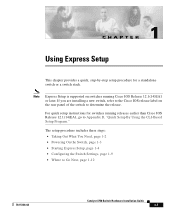
... switches running Cisco IOS Release 12.1(14)EA1 or later. Note Express Setup is supported on the rear panel of the switch to determine the release. If you are installing a new switch, refer to the Cisco IOS release label on switches running releases earlier than Cisco IOS Release 12.1(14)EA1, go to Go Next, page 1-12 78-15136-02 Catalyst...
... switches running Cisco IOS Release 12.1(14)EA1 or later. Note Express Setup is supported on the rear panel of the switch to determine the release. If you are installing a new switch, refer to the Cisco IOS release label on switches running releases earlier than Cisco IOS Release 12.1(14)EA1, go to Go Next, page 1-12 78-15136-02 Catalyst...

Hardware Installation Guide
Page 36
... on the other end of the connection. Catalyst 3750 Switch Hardware Installation Guide 1-8 78-15136-02 If not, make sure that POST successfully ran before starting Express Setup? To configure the switch by default. Note On switches running Cisco IOS Release 12.1(14)EA1 or later, you verify that ...browser, and press Enter. • Did you connect a crossover instead of a straight-through cable for this chapter explains how to configure a switch by using the command-line interface (CLI)-based setup program, see Appendix D, "Quick Setup By Using the CLI-Based Setup Program." Wait 30...
... on the other end of the connection. Catalyst 3750 Switch Hardware Installation Guide 1-8 78-15136-02 If not, make sure that POST successfully ran before starting Express Setup? To configure the switch by default. Note On switches running Cisco IOS Release 12.1(14)EA1 or later, you verify that ...browser, and press Enter. • Did you connect a crossover instead of a straight-through cable for this chapter explains how to configure a switch by using the command-line interface (CLI)-based setup program, see Appendix D, "Quick Setup By Using the CLI-Based Setup Program." Wait 30...
Hardware Installation Guide
Page 38
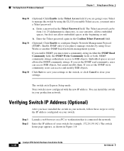
..., but cannot modify them. Enter a password in Figure 1-8. 1-10 Catalyst 3750 Switch Hardware Installation Guide 78-15136-02 Enable SNMP only if you are not allowed in your production network. Your switch is now configured with the new IP address. Enter the IP address ...Cisco Works or another SNMP-based network-management system. If you must enter a community string in the Confirm Telnet Password field. (Optional) Click Enable to configure Simple Network Management Protocol (SNMP). Verifying Switch IP Address (Optional) Chapter 1 Using Express Setup Step 10 Step 11 Step 12...
..., but cannot modify them. Enter a password in Figure 1-8. 1-10 Catalyst 3750 Switch Hardware Installation Guide 78-15136-02 Enable SNMP only if you are not allowed in your production network. Your switch is now configured with the new IP address. Enter the IP address ...Cisco Works or another SNMP-based network-management system. If you must enter a community string in the Confirm Telnet Password field. (Optional) Click Enable to configure Simple Network Management Protocol (SNMP). Verifying Switch IP Address (Optional) Chapter 1 Using Express Setup Step 10 Step 11 Step 12...
Hardware Installation Guide
Page 40
..., as Telnet and Extended Ping. • Help Resources-Access Catalyst 3750 documentation. and port-level settings. Installing or Connecting Devices to the Switch For detailed installation procedures on mounting your configuration to the switch software configuration guide For CMS requirements, see Chapter 3, "Installation." 1-12 Catalyst 3750 Switch Hardware Installation Guide 78-15136-02 Where to Go...
..., as Telnet and Extended Ping. • Help Resources-Access Catalyst 3750 documentation. and port-level settings. Installing or Connecting Devices to the Switch For detailed installation procedures on mounting your configuration to the switch software configuration guide For CMS requirements, see Chapter 3, "Installation." 1-12 Catalyst 3750 Switch Hardware Installation Guide 78-15136-02 Where to Go...

Hardware Installation Guide
Page 42
... Ethernet ports and 4 SFP module slots - Catalyst 3750G-12S-12 SFP module slots • The switches support these SFP modules: - 1000BASE-SX - 1000BASE-LX - 1000BASE-T Note When installed in Catalyst 3750 switches, 1000BASE-T small form-factor pluggable (SFP) modules can stack up to the Catalyst 3750-24TS, 3750G-24T, 3750-48TS, and 3750G-12S switches. For 10/100/1000 ports, autonegotiates the...
... Ethernet ports and 4 SFP module slots - Catalyst 3750G-12S-12 SFP module slots • The switches support these SFP modules: - 1000BASE-SX - 1000BASE-LX - 1000BASE-T Note When installed in Catalyst 3750 switches, 1000BASE-T small form-factor pluggable (SFP) modules can stack up to the Catalyst 3750-24TS, 3750G-24T, 3750-48TS, and 3750G-12S switches. For 10/100/1000 ports, autonegotiates the...

Hardware Installation Guide
Page 43
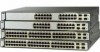
...the second member (port 2) on the Catalyst 3750G-24T and 3750G-24TS are numbered 1 (left , as shown in Figure 2-1. Figure 2-1 Catalyst 3750-24TS Front Panel 86541 SYST RPS MASTR STAT DUPLX SPEED STACK MODE 12 1X 34 56 78 9 10 11 12 11X 2X 12X 13 14 13X 15...the second member (port 2) on . Chapter 2 Product Overview Front Panel Description Note The Cisco RPS 300 does not support the Catalyst 3750G-24TS switch. - The first member of Catalyst 3750 switches. Front Panel Description The Catalyst 3750-24TS 10/100 ports are numbered 25 to the family of the pair (port ...
...the second member (port 2) on the Catalyst 3750G-24T and 3750G-24TS are numbered 1 (left , as shown in Figure 2-1. Figure 2-1 Catalyst 3750-24TS Front Panel 86541 SYST RPS MASTR STAT DUPLX SPEED STACK MODE 12 1X 34 56 78 9 10 11 12 11X 2X 12X 13 14 13X 15...the second member (port 2) on . Chapter 2 Product Overview Front Panel Description Note The Cisco RPS 300 does not support the Catalyst 3750G-24TS switch. - The first member of Catalyst 3750 switches. Front Panel Description The Catalyst 3750-24TS 10/100 ports are numbered 25 to the family of the pair (port ...

Hardware Installation Guide
Page 44
... 18 19 20 21 22 23 24 23X 14X 24X 1 Catalyst 3750 SERIES 1 10/100/1000 ports Figure 2-3 Catalyst 3750G-24TS Front Panel Chapter 2 Product Overview 86543 86544 SYST RPS MASTR STAT DUPLX SPEED STACK MODE 12 1X 34 56 78 9 10 11 12 11X 2X 12X 13 14 13X 15 16 17 18 19... 20 21 22 23 24 23X 14X 24X Catalyst 3750 SERIES 25 26 27 28 1 2 1 10/100 ports 2 SFP module ports The Catalyst 3750G-12S SFP module slots are grouped in three sets of four, as shown in Figure 2-4. Catalyst 3750 Switch Hardware Installation Guide 2-4 78-15136-02
... 18 19 20 21 22 23 24 23X 14X 24X 1 Catalyst 3750 SERIES 1 10/100/1000 ports Figure 2-3 Catalyst 3750G-24TS Front Panel Chapter 2 Product Overview 86543 86544 SYST RPS MASTR STAT DUPLX SPEED STACK MODE 12 1X 34 56 78 9 10 11 12 11X 2X 12X 13 14 13X 15 16 17 18 19... 20 21 22 23 24 23X 14X 24X Catalyst 3750 SERIES 25 26 27 28 1 2 1 10/100 ports 2 SFP module ports The Catalyst 3750G-12S SFP module slots are grouped in three sets of four, as shown in Figure 2-4. Catalyst 3750 Switch Hardware Installation Guide 2-4 78-15136-02

Hardware Installation Guide
Page 45
... are numbered 1 through 48. The ports are grouped in Figure 2-1. Chapter 2 Product Overview Figure 2-4 Catalyst 3750G-12S Front Panel Front Panel Description 97166 SYST RPS MASTR STAT DUPLX SPEED STACK MODE 1 2 3 4 5 6 7 8 9 10 Catalyst 3750 SERIES 11 12 1 1 SFP module ports The Catalyst 3750-48TS 10/100 ports are 1 (top) and 2 (bottom) and so on. Figure... 31 32 33 34 31X 33X 35 36 37 38 39 40 41 42 43 44 45 46 47 48 47X 32X 34X 48X Catalyst 3750 SERIES 1 3 2 4 1 2 1 10/100 ports 2 SFP module ports 78-15136-02 Catalyst 3750 Switch Hardware Installation Guide 2-5
... are numbered 1 through 48. The ports are grouped in Figure 2-1. Chapter 2 Product Overview Figure 2-4 Catalyst 3750G-12S Front Panel Front Panel Description 97166 SYST RPS MASTR STAT DUPLX SPEED STACK MODE 1 2 3 4 5 6 7 8 9 10 Catalyst 3750 SERIES 11 12 1 1 SFP module ports The Catalyst 3750-48TS 10/100 ports are 1 (top) and 2 (bottom) and so on. Figure... 31 32 33 34 31X 33X 35 36 37 38 39 40 41 42 43 44 45 46 47 48 47X 32X 34X 48X Catalyst 3750 SERIES 1 3 2 4 1 2 1 10/100 ports 2 SFP module ports 78-15136-02 Catalyst 3750 Switch Hardware Installation Guide 2-5

Hardware Installation Guide
Page 46
...for the cables are described in Appendix B, "Connector and Cable Specifications." When the automatic crossover feature is a straight-through cable. Catalyst 3750 Switch Hardware Installation Guide 2-6 78-15136-02 The automatic crossover feature is autonegotiate.) When set the 10/100/1000 ports to workstations, ... in the CLI to the switch software configuration guide or the switch command reference. When connecting the switch to operate in 10 Mbps, 100 Mbps, or 1000 Mbps in any combination of the connection. Note On switches running Cisco IOS Release 12.1(14)EA1 or later, you...
...for the cables are described in Appendix B, "Connector and Cable Specifications." When the automatic crossover feature is a straight-through cable. Catalyst 3750 Switch Hardware Installation Guide 2-6 78-15136-02 The automatic crossover feature is autonegotiate.) When set the 10/100/1000 ports to workstations, ... in the CLI to the switch software configuration guide or the switch command reference. When connecting the switch to operate in 10 Mbps, 100 Mbps, or 1000 Mbps in any combination of the connection. Note On switches running Cisco IOS Release 12.1(14)EA1 or later, you...

Hardware Installation Guide
Page 48
Figure 2-6 shows the Catalyst 3750-24TS, 3750G-24T, 3750G-24TS, 3750G-12S, and 3750-48TS LEDs and the Mode button that you use CMS to configure and monitor individual switches and switch clusters. All of the port modes. The switch software guide describes how to use to monitor switch activity and its performance. Figure 2-6 Catalyst 3750 LEDs SYST RPS MASTR STAT...
Figure 2-6 shows the Catalyst 3750-24TS, 3750G-24T, 3750G-24TS, 3750G-12S, and 3750-48TS LEDs and the Mode button that you use CMS to configure and monitor individual switches and switch clusters. All of the port modes. The switch software guide describes how to use to monitor switch activity and its performance. Figure 2-6 Catalyst 3750 LEDs SYST RPS MASTR STAT...
Hardware Installation Guide
Page 51
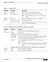
This is operating in full duplex. 78-15136-02 Catalyst 3750 Switch Hardware Installation Guide 2-11 Table 2-5 Meaning of LED Colors in ... duplex or half duplex. Green Port is not forwarding data. See the "Stack LED" section on the Switch Port Mode STAT (port status) DUPLX (duplex) LED Color Meaning Off No link, or port was administratively... transmitting or receiving data. Note The 10/100/1000 ports operate only in Different Modes on page 2-12 for a link-fault indication. Port is transmitting or receiving packets. Flashing amber Port is blocked by Spanning...
This is operating in full duplex. 78-15136-02 Catalyst 3750 Switch Hardware Installation Guide 2-11 Table 2-5 Meaning of LED Colors in ... duplex or half duplex. Green Port is not forwarding data. See the "Stack LED" section on the Switch Port Mode STAT (port status) DUPLX (duplex) LED Color Meaning Off No link, or port was administratively... transmitting or receiving data. Note The 10/100/1000 ports operate only in Different Modes on page 2-12 for a link-fault indication. Port is transmitting or receiving packets. Flashing amber Port is blocked by Spanning...

Hardware Installation Guide
Page 52
... member number. (stack member) Flashing Green Selected switch's member number. The first nine port LEDs show the status for StackWise ports 1 and 2, respectively. 2-12 Catalyst 3750 Switch Hardware Installation Guide 78-15136-02 The other stack member switches. SFP ports Off Port is operating at 100 Mbps.... The port LEDs 3 and 4 are down: • SFP port LEDs 1 and 2 on the Catalyst 3750-24TS switch show the position of a switch in a stack. Note When installed in Catalyst 3750 switches, 1000BASE-T SFP modules can be members of a stack. When the stack LED is operating at 1000 Mbps...
... member number. (stack member) Flashing Green Selected switch's member number. The first nine port LEDs show the status for StackWise ports 1 and 2, respectively. 2-12 Catalyst 3750 Switch Hardware Installation Guide 78-15136-02 The other stack member switches. SFP ports Off Port is operating at 100 Mbps.... The port LEDs 3 and 4 are down: • SFP port LEDs 1 and 2 on the Catalyst 3750-24TS switch show the position of a switch in a stack. Note When installed in Catalyst 3750 switches, 1000BASE-T SFP modules can be members of a stack. When the stack LED is operating at 1000 Mbps...

Hardware Installation Guide
Page 53
...and 2, respectively. • The 10/100/1000 port LEDs 23 and 24 on the Catalyst 3750G-24T switch show the status for StackWise ports 1 and 2, respectively. If any of the port LEDs are green on the Catalyst 3750G-12S switch show the status for StackWise ports 1 and 2, respectively. • SFP port LEDs ...11 and 12 on all the switches in the stack, the stack is not operating at full bandwidth (32 Gbps). Figure ...
...and 2, respectively. • The 10/100/1000 port LEDs 23 and 24 on the Catalyst 3750G-24T switch show the status for StackWise ports 1 and 2, respectively. If any of the port LEDs are green on the Catalyst 3750G-12S switch show the status for StackWise ports 1 and 2, respectively. • SFP port LEDs ...11 and 12 on all the switches in the stack, the stack is not operating at full bandwidth (32 Gbps). Figure ...

Hardware Installation Guide
Page 54
Rear Panel Description Chapter 2 Product Overview Rear Panel Description The switch rear panels have an AC power connector, an RPS connector, an RJ-45 console port, and two StackWise ports. (See Figure 2-8 and Figure 2-9.) Figure 2-8 Catalyst 3750-24TS, 3750G-24T, 3750G-12S, and 3750-48TS Rear Panel 86548 STACK 1 STACK 2 CONSOLE 1.6A-100R>09A-A2T0,IN05GV0...
Rear Panel Description Chapter 2 Product Overview Rear Panel Description The switch rear panels have an AC power connector, an RPS connector, an RJ-45 console port, and two StackWise ports. (See Figure 2-8 and Figure 2-9.) Figure 2-8 Catalyst 3750-24TS, 3750G-24T, 3750G-12S, and 3750-48TS Rear Panel 86548 STACK 1 STACK 2 CONSOLE 1.6A-100R>09A-A2T0,IN05GV0...

Hardware Installation Guide
Page 56
... an AC power outlet. Cisco RPS Connector Specific Cisco RPS modes support specific Catalyst 3750 switches: • Cisco RPS 300 (model PWR300-AC-RPS-N1) supports the Catalyst 3750-24TS, 3750G-24T, 3750G-12S, and 3750-48TS switches. • Cisco RPS 675 (model PWR675-AC-RPS-N1=) supports the Catalyst 3750 family of 300W. Cisco RPS 300 The Cisco RPS 300 has two output...
... an AC power outlet. Cisco RPS Connector Specific Cisco RPS modes support specific Catalyst 3750 switches: • Cisco RPS 300 (model PWR300-AC-RPS-N1) supports the Catalyst 3750-24TS, 3750G-24T, 3750G-12S, and 3750-48TS switches. • Cisco RPS 675 (model PWR675-AC-RPS-N1=) supports the Catalyst 3750 family of 300W. Cisco RPS 300 The Cisco RPS 300 has two output...

Hardware Installation Guide
Page 61
... considerations to keep in this order: • Preparing for Installation, page 3-1 • Verifying Switch Operation, page 3-8 • Planning the Stack, page 3-12 • Installing the Switch, page 3-17 • Connecting StackWise Cable to StackWise Ports, page 3-37 • Connecting ...3-2 • EMC Regulatory Statements, page 3-4 • Installation Guidelines, page 3-6 78-15136-02 Catalyst 3750 Switch Hardware Installation Guide 3-1 It describes how to install the switch and make connections to interpret the power-on self-test (POST) that ensures proper operation. Read the...
... considerations to keep in this order: • Preparing for Installation, page 3-1 • Verifying Switch Operation, page 3-8 • Planning the Stack, page 3-12 • Installing the Switch, page 3-17 • Connecting StackWise Cable to StackWise Ports, page 3-37 • Connecting ...3-2 • EMC Regulatory Statements, page 3-4 • Installation Guidelines, page 3-6 78-15136-02 Catalyst 3750 Switch Hardware Installation Guide 3-1 It describes how to install the switch and make connections to interpret the power-on self-test (POST) that ensures proper operation. Read the...
