Hardware Installation Guide
Page 21
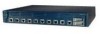
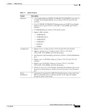
...Catalyst 3550-12T and 3550-12G switches) • Supports up to 8,000 MAC addresses (Catalyst 3550-24, 3550-24DC, 3550-24-FX, 3550-24PWR, and 3550-48 switches) • Checks for errors on a received packet, determines the destination port, stores the packet in shared memory, and then forwards the packet to the destination port • Connection for optional Cisco RPS 300 redundant power... system or the Cisco RPS 675 redundant power system that operates on AC input and supplies backup DC power to the switch OL-6155-01 Catalyst 3550 Switch Hardware ...
...Catalyst 3550-12T and 3550-12G switches) • Supports up to 8,000 MAC addresses (Catalyst 3550-24, 3550-24DC, 3550-24-FX, 3550-24PWR, and 3550-48 switches) • Checks for errors on a received packet, determines the destination port, stores the packet in shared memory, and then forwards the packet to the destination port • Connection for optional Cisco RPS 300 redundant power... system or the Cisco RPS 675 redundant power system that operates on AC input and supplies backup DC power to the switch OL-6155-01 Catalyst 3550 Switch Hardware ...

Hardware Installation Guide
Page 25
... Cisco Systems. The internal power supply in different port modes. See the "Clearing the Switch IP Address and Configuration" section on the RPS, and the LED should turn green. Table 1-4 Port Mode LEDs Mode LED STATUS UTIL1 DUPLX Port Mode Port status Switch utilization Port duplex mode Description The port status. OL-6155-01 Catalyst 3550 Switch Hardware...
... Cisco Systems. The internal power supply in different port modes. See the "Clearing the Switch IP Address and Configuration" section on the RPS, and the LED should turn green. Table 1-4 Port Mode LEDs Mode LED STATUS UTIL1 DUPLX Port Mode Port status Switch utilization Port duplex mode Description The port status. OL-6155-01 Catalyst 3550 Switch Hardware...
Hardware Installation Guide
Page 29
... a Cisco RPS to the switch. These Cisco RPS models support the Catalyst 3550 switches: • Cisco RPS 300 (model PWR300-AC-RPS-N1) supports the Catalyst 3550-12T, 3550-12G, 3550-24, 3550-FX, and 3550-48 switches. • Cisco RPS 675 (model PWR675-AC-RPS-N1) supports the Catalyst 3550-12T, 3550-12G, 3550-24, 3550-FX, 3550-24PWR, and 3550-48 switches. Chapter 1 Product Overview Management Options AC Power Connector For AC-powered switches, the internal power supply...
... a Cisco RPS to the switch. These Cisco RPS models support the Catalyst 3550 switches: • Cisco RPS 300 (model PWR300-AC-RPS-N1) supports the Catalyst 3550-12T, 3550-12G, 3550-24, 3550-FX, and 3550-48 switches. • Cisco RPS 675 (model PWR675-AC-RPS-N1) supports the Catalyst 3550-12T, 3550-12G, 3550-24, 3550-FX, 3550-24PWR, and 3550-48 switches. Chapter 1 Product Overview Management Options AC Power Connector For AC-powered switches, the internal power supply...

Hardware Installation Guide
Page 44
...-kit envelope. Place the switch on a wall with the front panel facing up . Statement 266 Figure 2-17 Mounting the Switch on a Wall Catalyst 3550 11 12 1 2 3 4 5 6 7 8 9 10 MODE SPEEDDUPLX USTITLATUS RSPYSSTEM User-supplied screws 60967 User-supplied screws Table or Shelf Mounting...Locate the adhesive strip with safety regulations, mount the switches on the table or shelf near an AC power source. 2-14 Catalyst 3550 Switch Hardware Installation Guide OL-6155-01 Installing the Switch Chapter 2 Switch Installation Mounting the Switch on a Wall For the best support of the...
...-kit envelope. Place the switch on a wall with the front panel facing up . Statement 266 Figure 2-17 Mounting the Switch on a Wall Catalyst 3550 11 12 1 2 3 4 5 6 7 8 9 10 MODE SPEEDDUPLX USTITLATUS RSPYSSTEM User-supplied screws 60967 User-supplied screws Table or Shelf Mounting...Locate the adhesive strip with safety regulations, mount the switches on the table or shelf near an AC power source. 2-14 Catalyst 3550 Switch Hardware Installation Guide OL-6155-01 Installing the Switch Chapter 2 Switch Installation Mounting the Switch on a Wall For the best support of the...

Hardware Installation Guide
Page 46
...Powering the Switch Use the supplied AC power cord to connect the AC power socket on the Switch DC OUTPUT 1 100-240V~ 5-3A 50/60Hz CONSOLE 93286 Torque to 15 lbf-in .) Figure 2-18 Torquing Ground-Lug Screws on the switch rear panel to an AC power outlet. If the switch...in. (240 ozf-in . When the switch powers on, it automatically begins the power-on self-test (POST), a series of action. 2-16 Catalyst 3550 Switch Hardware Installation Guide OL-6155-01 Powering the Switch and Connecting Devices These sections describe powering the switch, connecting an RPS, connecting cables, and...
...Powering the Switch Use the supplied AC power cord to connect the AC power socket on the Switch DC OUTPUT 1 100-240V~ 5-3A 50/60Hz CONSOLE 93286 Torque to 15 lbf-in .) Figure 2-18 Torquing Ground-Lug Screws on the switch rear panel to an AC power outlet. If the switch...in. (240 ozf-in . When the switch powers on, it automatically begins the power-on self-test (POST), a series of action. 2-16 Catalyst 3550 Switch Hardware Installation Guide OL-6155-01 Powering the Switch and Connecting Devices These sections describe powering the switch, connecting an RPS, connecting cables, and...
Hardware Installation Guide
Page 47
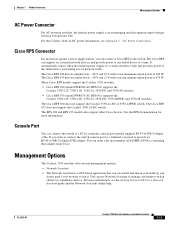
...-pinout descriptions. Note Make sure to connect the switch and the RPS to the Ethernet ports. Chapter 2 Switch Installation Powering the Switch and Connecting Devices Connecting a Cisco RPS Use the cable supplied with the RPS to connect to the same AC power source. OL-6155-01 Catalyst 3550 Switch Hardware Installation Guide 2-17 Connect the switch and the RPS to the...
...-pinout descriptions. Note Make sure to connect the switch and the RPS to the Ethernet ports. Chapter 2 Switch Installation Powering the Switch and Connecting Devices Connecting a Cisco RPS Use the cable supplied with the RPS to connect to the same AC power source. OL-6155-01 Catalyst 3550 Switch Hardware Installation Guide 2-17 Connect the switch and the RPS to the...
Hardware Installation Guide
Page 68
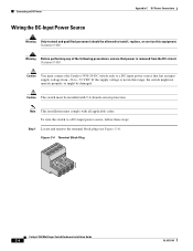
Figure C-4 Terminal Block Plug 60530 Catalyst 3550 Multilayer Switch Hardware Installation Guide C-4 OL-6155-01 Caution The switch must be damaged. If the supply voltage is removed from -36 to a DC-input power source, follow these steps: Step 1 Locate and remove the terminal block plug (see Figure C-4). Statement 1003 Caution You must comply with 5 A-branch-circuit protection...
Figure C-4 Terminal Block Plug 60530 Catalyst 3550 Multilayer Switch Hardware Installation Guide C-4 OL-6155-01 Caution The switch must be damaged. If the supply voltage is removed from -36 to a DC-input power source, follow these steps: Step 1 Locate and remove the terminal block plug (see Figure C-4). Statement 1003 Caution You must comply with 5 A-branch-circuit protection...

Hardware Installation Guide
Page 74
...-Emulation Software" section on page D-3 • "Powering on the Switch" section on page D-4 Connecting to the Console Port Follow these steps to connect the PC or terminal to the switch console port: Step 1 Step 2 Using the supplied RJ-45-to the terminal. Attach the DB-9 female...enter the write memory command. Accessing the CLI Through the Console Port Appendix D Configuring the Switch with the CLI-Based Setup Program Note While in Figure D-1. Catalyst 3550 Multilayer Switch Hardware Installation Guide D-2 OL-6155-01 Accessing the CLI Through the Console Port You can access...
...-Emulation Software" section on page D-3 • "Powering on the Switch" section on page D-4 Connecting to the Console Port Follow these steps to connect the PC or terminal to the switch console port: Step 1 Step 2 Using the supplied RJ-45-to the terminal. Attach the DB-9 female...enter the write memory command. Accessing the CLI Through the Console Port Appendix D Configuring the Switch with the CLI-Based Setup Program Note While in Figure D-1. Catalyst 3550 Multilayer Switch Hardware Installation Guide D-2 OL-6155-01 Accessing the CLI Through the Console Port You can access...

Hardware Installation Guide
Page 76
...the Initial Configuration Information To set up the switch, you powered on the switch rear panel. See these steps to power on the switch: Step 1 Step 2 Connect one end of the supplied AC power cord to the power connector on your network administrator before you ...power cable to display the setup program prompt. This information is also required if you complete the setup program: • Switch IP address • Subnet mask (IP netmask) • Default gateway (router) • Enable secret password • Enable password • Telnet password Catalyst 3550 Multilayer Switch...
...the Initial Configuration Information To set up the switch, you powered on the switch rear panel. See these steps to power on the switch: Step 1 Step 2 Connect one end of the supplied AC power cord to the power connector on your network administrator before you ...power cable to display the setup program prompt. This information is also required if you complete the setup program: • Switch IP address • Subnet mask (IP netmask) • Default gateway (router) • Enable secret password • Enable password • Telnet password Catalyst 3550 Multilayer Switch...

Hardware Installation Guide
Page 84
... 3-16, D-4 DC connector 2-10 IN-4 Catalyst 3550 Multilayer Switch Hardware Installation Guide RPS connector 2-10 specifications A-2 powering the switch 3-16 procedures AC grounding 3-15 to 3-16 DC grounding C-2 to C-3 installation 3-5 to 3-14 publications, related xiii, xiii to xiv R rack-mounting 3-5 to 3-12 rear panel clearance 3-4 description 2-10 to 2-11 redundant power supply See RPS related publications xiii...
... 3-16, D-4 DC connector 2-10 IN-4 Catalyst 3550 Multilayer Switch Hardware Installation Guide RPS connector 2-10 specifications A-2 powering the switch 3-16 procedures AC grounding 3-15 to 3-16 DC grounding C-2 to C-3 installation 3-5 to 3-14 publications, related xiii, xiii to xiv R rack-mounting 3-5 to 3-12 rear panel clearance 3-4 description 2-10 to 2-11 redundant power supply See RPS related publications xiii...

