Hardware Installation Guide
Page 4
... Requirements 3-4 Verifying Package Contents 3-4 Installing the Switch 3-5 Rack-Mounting 3-5 Attaching Brackets to the Catalyst 3550-12T and 3550-12G Switches 3-6 Attaching Brackets to the Catalyst 3550-24, 3550-24-DC, 3550-24-FX, 3550-24PWR, and 3550-48 Switches 3-8 Mounting the Switch in a Rack 3-12 Wall Mounting 3-12 Attaching the Brackets to the Switch 3-13 Attaching the RPS Connector Cover 3-13 Mounting the Switch on a Wall 3-14 Table or Shelf...
... Requirements 3-4 Verifying Package Contents 3-4 Installing the Switch 3-5 Rack-Mounting 3-5 Attaching Brackets to the Catalyst 3550-12T and 3550-12G Switches 3-6 Attaching Brackets to the Catalyst 3550-24, 3550-24-DC, 3550-24-FX, 3550-24PWR, and 3550-48 Switches 3-8 Mounting the Switch in a Rack 3-12 Wall Mounting 3-12 Attaching the Brackets to the Switch 3-13 Attaching the RPS Connector Cover 3-13 Mounting the Switch on a Wall 3-14 Table or Shelf...
Hardware Installation Guide
Page 21
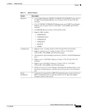
...Catalyst 3550-12T and 3550-12G switches) • Supports up to 8,000 MAC addresses (Catalyst 3550-24, 3550-24DC, 3550-24-FX, 3550-24PWR, and 3550-48 switches) • Checks for errors on a received packet, determines the destination port, stores the packet in shared memory, and then forwards the packet to the destination port • Connection for optional Cisco... RPS 300 redundant power system or the Cisco RPS 675 redundant power system that operates on AC input and supplies backup DC power to the switch OL-6155-01 Catalyst 3550 Switch Hardware Installation Guide...
...Catalyst 3550-12T and 3550-12G switches) • Supports up to 8,000 MAC addresses (Catalyst 3550-24, 3550-24DC, 3550-24-FX, 3550-24PWR, and 3550-48 switches) • Checks for errors on a received packet, determines the destination port, stores the packet in shared memory, and then forwards the packet to the destination port • Connection for optional Cisco... RPS 300 redundant power system or the Cisco RPS 675 redundant power system that operates on AC input and supplies backup DC power to the switch OL-6155-01 Catalyst 3550 Switch Hardware Installation Guide...

Hardware Installation Guide
Page 27
... the LEDs on the Catalyst 3550-24 and 3550-24-DC switches. Note The port LEDs on the Catalyst 3550-48 switch. Figure 1-5 Bandwidth Utilization for the Catalyst 3550-12T 74026 SYSTEM RPS STATUS UTIL DUPLX SPEED MODE 1 2 3 4 5 6 7 8 9 10 < 25% + 25% - 49% + 50% + Catalyst 3550 SERIES 1 2 Figure 1-5 shows the bandwidth utilization percentages displayed by the LEDs on the Catalyst 3550-12G switch. OL-6155-01 Catalyst 3550 Switch Hardware Installation Guide...
... the LEDs on the Catalyst 3550-24 and 3550-24-DC switches. Note The port LEDs on the Catalyst 3550-48 switch. Figure 1-5 Bandwidth Utilization for the Catalyst 3550-12T 74026 SYSTEM RPS STATUS UTIL DUPLX SPEED MODE 1 2 3 4 5 6 7 8 9 10 < 25% + 25% - 49% + 50% + Catalyst 3550 SERIES 1 2 Figure 1-5 shows the bandwidth utilization percentages displayed by the LEDs on the Catalyst 3550-12G switch. OL-6155-01 Catalyst 3550 Switch Hardware Installation Guide...

Hardware Installation Guide
Page 28
... percentages displayed by the LEDs on the Catalyst 3550-24-FX switch. 74099 Figure 1-8 Bandwidth Utilization for the Catalyst 3550-24-FX SYSTEM RPS STATUS UTIL DUPLX SPEED MODE < 25% + 25% - 49% + 50% + Catalyst 3550 SERIES 1 2 Rear-Panel Description Other than the Catalyst 3550-24-DC switch, the switch rear panels have similar components. Note Figure 1-9 shows the Catalyst 3550-12T switch as the terminal block header), an RJ...
... percentages displayed by the LEDs on the Catalyst 3550-24-FX switch. 74099 Figure 1-8 Bandwidth Utilization for the Catalyst 3550-24-FX SYSTEM RPS STATUS UTIL DUPLX SPEED MODE < 25% + 25% - 49% + 50% + Catalyst 3550 SERIES 1 2 Rear-Panel Description Other than the Catalyst 3550-24-DC switch, the switch rear panels have similar components. Note Figure 1-9 shows the Catalyst 3550-12T switch as the terminal block header), an RJ...
Hardware Installation Guide
Page 29
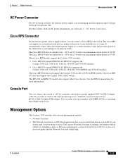
... 240 VAC. The Cisco RPS 300 does not support the Catalyst 3550-24-DC or 3550-24PWR switch. See the RPS documentation for more information, see Appendix C, "DC Power Connections." You can...switch console port to a terminal, you can use Network Assistant to the switch. These Cisco RPS models support the Catalyst 3550 switches: • Cisco RPS 300 (model PWR300-AC-RPS-N1) supports the Catalyst 3550-12T, 3550-12G, 3550-24, 3550-FX, and 3550-48 switches. • Cisco RPS 675 (model PWR675-AC-RPS-N1) supports the Catalyst 3550-12T, 3550-12G, 3550-24, 3550-FX, 3550-24PWR, and 3550-48 switches...
... 240 VAC. The Cisco RPS 300 does not support the Catalyst 3550-24-DC or 3550-24PWR switch. See the RPS documentation for more information, see Appendix C, "DC Power Connections." You can...switch console port to a terminal, you can use Network Assistant to the switch. These Cisco RPS models support the Catalyst 3550 switches: • Cisco RPS 300 (model PWR300-AC-RPS-N1) supports the Catalyst 3550-12T, 3550-12G, 3550-24, 3550-FX, and 3550-48 switches. • Cisco RPS 675 (model PWR675-AC-RPS-N1) supports the Catalyst 3550-12T, 3550-12G, 3550-24, 3550-FX, 3550-24PWR, and 3550-48 switches...
Hardware Installation Guide
Page 33
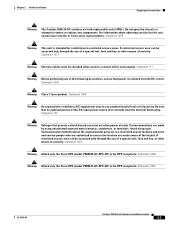
...users and service people who are authorized to the RPS receptacle. Statement 100C OL-6155-01 Catalyst 3550 Switch Hardware Installation Guide 2-3 Chapter 2 Switch Installation Preparing for Installation Warning The Catalyst 3550-24-DC contains no exposed portion of electricity. A restricted access area can exist on inline power ...be shielded when used in restricted access areas. Statement 1003 Warning Class 1 laser product. Statement 100B Warning Attach only the Cisco RPS (model PWR675-AC-RPS-N1) to access the location are made aware of security. Be sure that present a ...
...users and service people who are authorized to the RPS receptacle. Statement 100C OL-6155-01 Catalyst 3550 Switch Hardware Installation Guide 2-3 Chapter 2 Switch Installation Preparing for Installation Warning The Catalyst 3550-24-DC contains no exposed portion of electricity. A restricted access area can exist on inline power ...be shielded when used in restricted access areas. Statement 1003 Warning Class 1 laser product. Statement 100B Warning Attach only the Cisco RPS (model PWR675-AC-RPS-N1) to access the location are made aware of security. Be sure that present a ...
Hardware Installation Guide
Page 34
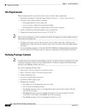
... Note If the switch is installed in Appendix A, "Technical Specifications." • Clearance to front and rear panels is missing or damaged, contact your Cisco representative or reseller for..., and fluorescent lighting fixtures. Access to the switch (Catalyst 3550-12T and 3550-12G switches) - Four Phillips machine screws for mounting the switch on a table - Six Phillips flat-head screws... damage the cables. • For sites requiring compliance to the switch (Catalyst 3550-24, 3550-24-DC, 3550-24-FX, 3550-24PWR, and 3550-48 switches) - Return all 10/100 and 10/100/1000 ports must ...
... Note If the switch is installed in Appendix A, "Technical Specifications." • Clearance to front and rear panels is missing or damaged, contact your Cisco representative or reseller for..., and fluorescent lighting fixtures. Access to the switch (Catalyst 3550-12T and 3550-12G switches) - Four Phillips machine screws for mounting the switch on a table - Six Phillips flat-head screws... damage the cables. • For sites requiring compliance to the switch (Catalyst 3550-24, 3550-24-DC, 3550-24-FX, 3550-24PWR, and 3550-48 switches) - Return all 10/100 and 10/100/1000 ports must ...
Hardware Installation Guide
Page 35
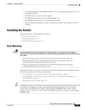
... Catalyst 3550-12T and 3550-12G Switches, page 2-6 • Attaching Brackets to one of the rack. • If the rack is the only unit in the rack. • When mounting this unit in a partially filled rack, load the rack from Cisco. One RPS connector cover (for attaching the cable guide to the Catalyst 3550-24, 3550-24-DC, 3550-24-FX, 3550-24PWR, and 3550-48 Switches...
... Catalyst 3550-12T and 3550-12G Switches, page 2-6 • Attaching Brackets to one of the rack. • If the rack is the only unit in the rack. • When mounting this unit in a partially filled rack, load the rack from Cisco. One RPS connector cover (for attaching the cable guide to the Catalyst 3550-24, 3550-24-DC, 3550-24-FX, 3550-24PWR, and 3550-48 Switches...

Hardware Installation Guide
Page 38
...supplied Phillips flat-head screws, as shown in Figure 2-7. Catalyst 3550 Switch Hardware Installation Guide 2-8 OL-6155-01 Note Before you attach the brackets on the Catalyst 3550-24-FX switch, remove the screws that you are on whether you use... flat-head screws Figure 2-6 Attaching Brackets for 24-Inch Telco Racks 74035 2 3 4 5 6 Catalyst 3550 SERIES 7 8 9 10 11 12 24" Configuration Phillips flat-head screws 74040 Attaching Brackets to the Catalyst 3550-24, 3550-24-DC, 3550-24-FX, 3550-24PWR, and 3550-48 Switches The bracket orientation and the brackets that are ...
...supplied Phillips flat-head screws, as shown in Figure 2-7. Catalyst 3550 Switch Hardware Installation Guide 2-8 OL-6155-01 Note Before you attach the brackets on the Catalyst 3550-24-FX switch, remove the screws that you are on whether you use... flat-head screws Figure 2-6 Attaching Brackets for 24-Inch Telco Racks 74035 2 3 4 5 6 Catalyst 3550 SERIES 7 8 9 10 11 12 24" Configuration Phillips flat-head screws 74040 Attaching Brackets to the Catalyst 3550-24, 3550-24-DC, 3550-24-FX, 3550-24PWR, and 3550-48 Switches The bracket orientation and the brackets that are ...

Hardware Installation Guide
Page 43
... an RPS is not connected to the switch, install an RPS connector cover on the Switch 86483 DC OUTPUT 1 RPS pPanh-ilhliepasdcocnonveecrtor RPS screws connector 100-240V~ 5-3A 50/60Hz CONSOLE OL-6155-01 Catalyst 3550 Switch Hardware Installation Guide 2-13 Chapter 2 Switch Installation Installing the Switch Attaching the Brackets to the Switch Figure 2-15 shows how to attach...
... an RPS is not connected to the switch, install an RPS connector cover on the Switch 86483 DC OUTPUT 1 RPS pPanh-ilhliepasdcocnonveecrtor RPS screws connector 100-240V~ 5-3A 50/60Hz CONSOLE OL-6155-01 Catalyst 3550 Switch Hardware Installation Guide 2-13 Chapter 2 Switch Installation Installing the Switch Attaching the Brackets to the Switch Figure 2-15 shows how to attach...
Hardware Installation Guide
Page 47
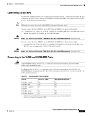
... switch models. • Catalyst 3550-12T, 3550-12G, 3550-24, 3550-FX, 3550-24PWR, or 3550-48 switch. (The Cisco RPS 675 does not support the Catalyst 3550-24-DC switch.) Warning Attach only the Cisco RPS (model PWR675-AC-RPS-N1) to the RPS receptacle. Statement 100B You can connect the Cisco RPS 675 (model PWR675-AC-RPS-N1) to these switch models: • Catalyst 3550-12T, 3550-12G, 3550-24, 3550-FX, or 3550-48 switch. (The Cisco...
... switch models. • Catalyst 3550-12T, 3550-12G, 3550-24, 3550-FX, 3550-24PWR, or 3550-48 switch. (The Cisco RPS 675 does not support the Catalyst 3550-24-DC switch.) Warning Attach only the Cisco RPS (model PWR675-AC-RPS-N1) to the RPS receptacle. Statement 100B You can connect the Cisco RPS 675 (model PWR675-AC-RPS-N1) to these switch models: • Catalyst 3550-12T, 3550-12G, 3550-24, 3550-FX, or 3550-48 switch. (The Cisco...

Hardware Installation Guide
Page 55
...This appendix lists the switch technical specifications in . (4.4 x 44 x 44 cm) OL-6155-01 Catalyst 3550 Multilayer Switch Hardware Installation Guide A-1 Table A-1 Switch Environmental and Physical ...Catalyst 3550-12T and 3550-12G: 16 lb (7.26 kg) Catalyst 3550-24: 11 lb (5 kg) Catalyst 3550-24-DC and 3550-24-FX: 10.5 lb (4.8 kg) Catalyst 3550-24PWR: 14 lb (6.35 kg) Catalyst 3550-48: 13 lb (5.9 kg) Catalyst 3550-12T and 3550-12G: 2.63 x 15.9 x 17.5 in. (6.68 x 40.39 x 44.45 cm) Catalyst 3550-24 and 3550-24-DC: 1.75 x 14.4 x 17.5 in. (4.45 x 36.58 x 44.45 cm) Catalyst 3550-24-FX and 3550...
...This appendix lists the switch technical specifications in . (4.4 x 44 x 44 cm) OL-6155-01 Catalyst 3550 Multilayer Switch Hardware Installation Guide A-1 Table A-1 Switch Environmental and Physical ...Catalyst 3550-12T and 3550-12G: 16 lb (7.26 kg) Catalyst 3550-24: 11 lb (5 kg) Catalyst 3550-24-DC and 3550-24-FX: 10.5 lb (4.8 kg) Catalyst 3550-24PWR: 14 lb (6.35 kg) Catalyst 3550-48: 13 lb (5.9 kg) Catalyst 3550-12T and 3550-12G: 2.63 x 15.9 x 17.5 in. (6.68 x 40.39 x 44.45 cm) Catalyst 3550-24 and 3550-24-DC: 1.75 x 14.4 x 17.5 in. (4.45 x 36.58 x 44.45 cm) Catalyst 3550-24-FX and 3550...
Hardware Installation Guide
Page 56
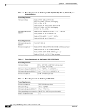
... Table A-2 Power Requirements for the Catalyst 3550-12T, 3550-12G, 3550-24, 3550-24-FX, and 3550-48 Switches Power Requirements AC input voltage DC input voltages for RPS 300 Power Requirements DC input voltages for RPS 675 Power consumption Catalyst 3550-12T and 3550-12G: 100 to 127/200 to 240 VAC (autoranging) 2 A/1 A, 50 to 60 Hz Catalyst 3550-24, 3550-24-FX, and 3550-48: 100 to 127/200 to...
... Table A-2 Power Requirements for the Catalyst 3550-12T, 3550-12G, 3550-24, 3550-24-FX, and 3550-48 Switches Power Requirements AC input voltage DC input voltages for RPS 300 Power Requirements DC input voltages for RPS 675 Power consumption Catalyst 3550-12T and 3550-12G: 100 to 127/200 to 240 VAC (autoranging) 2 A/1 A, 50 to 60 Hz Catalyst 3550-24, 3550-24-FX, and 3550-48: 100 to 127/200 to...
Hardware Installation Guide
Page 65
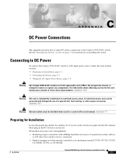
... Cisco sales representative. C A P P E N D I X DC Power Connections This appendix describes how to make DC power connections to remove or replace any components. Statement 121B Warning This unit is intended for instructions on page 2-5 for installation in the DC-switch accessory kit. See the "Installing the Switch" section on installing the switch. Connecting to DC Power To connect the Catalyst 3550-24-DC switch to a DC...
... Cisco sales representative. C A P P E N D I X DC Power Connections This appendix describes how to make DC power connections to remove or replace any components. Statement 121B Warning This unit is intended for instructions on page 2-5 for installation in the DC-switch accessory kit. See the "Installing the Switch" section on installing the switch. Connecting to DC Power To connect the Catalyst 3550-24-DC switch to a DC...
Hardware Installation Guide
Page 68
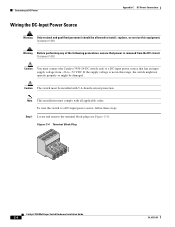
... applicable codes. Statement 1003 Caution You must connect the Catalyst 3550-24-DC switch only to a DC-input power source, follow these steps: Step 1 Locate and remove the terminal block plug (see Figure C-4). Caution The switch must comply with 5 A-branch-circuit protection. Figure C-4 Terminal Block Plug 60530 Catalyst 3550 Multilayer Switch Hardware Installation Guide C-4 OL-6155-01 Statement 1030 Warning...
... applicable codes. Statement 1003 Caution You must connect the Catalyst 3550-24-DC switch only to a DC-input power source, follow these steps: Step 1 Locate and remove the terminal block plug (see Figure C-4). Caution The switch must comply with 5 A-branch-circuit protection. Figure C-4 Terminal Block Plug 60530 Catalyst 3550 Multilayer Switch Hardware Installation Guide C-4 OL-6155-01 Statement 1030 Warning...

Hardware Installation Guide
Page 71
...Catalyst 3550-24-DC switch is suitable only for the wiring must be disturbed by casual contact. Caution Secure the wires coming in from the circuit-breaker switch handle, and move the circuit-breaker handle to DC Power 60534 Step 7 Insert the terminal block plug in the terminal block header on position. Appendix C DC..., intrabuilding wiring must be shielded, and the shield for intrabuilding or nonexposed wiring connections. OL-6155-01 Catalyst 3550 Multilayer Switch Hardware Installation Guide C-7 Figure C-10 Inserting the Terminal Block in Figure C-10. For example, use tie...
...Catalyst 3550-24-DC switch is suitable only for the wiring must be disturbed by casual contact. Caution Secure the wires coming in from the circuit-breaker switch handle, and move the circuit-breaker handle to DC Power 60534 Step 7 Insert the terminal block plug in the terminal block header on position. Appendix C DC..., intrabuilding wiring must be shielded, and the shield for intrabuilding or nonexposed wiring connections. OL-6155-01 Catalyst 3550 Multilayer Switch Hardware Installation Guide C-7 Figure C-10 Inserting the Terminal Block in Figure C-10. For example, use tie...
