
Hardware Installation Guide
Page 31
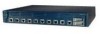
... is installed, the following ports must be allowed to install, replace, or service this equipment. Warning Only trained and qualified personnel should be connected through an approved network termination unit with integral circuit protection: 10/100 Ethernet. Statement 1044 OL-6155-01 Catalyst 3550 Switch Hardware Installation Guide 2-1 Statement 1030 Warning Read the installation...
... is installed, the following ports must be allowed to install, replace, or service this equipment. Warning Only trained and qualified personnel should be connected through an approved network termination unit with integral circuit protection: 10/100 Ethernet. Statement 1044 OL-6155-01 Catalyst 3550 Switch Hardware Installation Guide 2-1 Statement 1030 Warning Read the installation...

Hardware Installation Guide
Page 32
... should be accessible at least 3 inches (7.6 cm) of clearance around the ventilation openings. Statement 17B Warning When installing or replacing the unit, the ground connection must always be grounded. Statement 266 Catalyst 3550 Switch Hardware Installation Guide 2-2 OL-6155-01 If the chassis falls, it can cause serious burns or weld the metal object...
... should be accessible at least 3 inches (7.6 cm) of clearance around the ventilation openings. Statement 17B Warning When installing or replacing the unit, the ground connection must always be grounded. Statement 266 Catalyst 3550 Switch Hardware Installation Guide 2-2 OL-6155-01 If the chassis falls, it can cause serious burns or weld the metal object...
Hardware Installation Guide
Page 33
...) to the RPS receptacle. Statement 100B Warning Attach only the Cisco RPS (model PWR675-AC-RPS-N1) to the RPS receptacle. Statement 1003 Warning Class 1 laser product. Statement 100C OL-6155-01 Catalyst 3550 Switch Hardware Installation Guide 2-3 Statement 1017 Warning Ethernet cables must be... restricted access location and users and service people who are authorized to remove or replace any of the following procedures, ensure that power is intended for Installation Warning The Catalyst 3550-24-DC contains no exposed portion of the DC-input power source wire extends ...
...) to the RPS receptacle. Statement 100B Warning Attach only the Cisco RPS (model PWR675-AC-RPS-N1) to the RPS receptacle. Statement 1003 Warning Class 1 laser product. Statement 100C OL-6155-01 Catalyst 3550 Switch Hardware Installation Guide 2-3 Statement 1017 Warning Ethernet cables must be... restricted access location and users and service people who are authorized to remove or replace any of the following procedures, ensure that power is intended for Installation Warning The Catalyst 3550-24-DC contains no exposed portion of the DC-input power source wire extends ...

Hardware Installation Guide
Page 54
Replace it on another device. Use the show interfaces privileged EXEC command to within the distances listed in the "Front-Panel Description" section on page 1-6 for Cisco-recommended GBIC modules, and see your GBIC module documentation for more information. • There might be a speed and duplex autonegotiation mismatch. Reduce the cable ...appropriate Ethernet cable for the connected device. See Table 2-1 on page 2-17 for cabling requirements. • Verify that the cable is not recognizing a GBIC module. Catalyst 3550 Switch Hardware Installation Guide 3-4 OL-6155-01
Replace it on another device. Use the show interfaces privileged EXEC command to within the distances listed in the "Front-Panel Description" section on page 1-6 for Cisco-recommended GBIC modules, and see your GBIC module documentation for more information. • There might be a speed and duplex autonegotiation mismatch. Reduce the cable ...appropriate Ethernet cable for the connected device. See Table 2-1 on page 2-17 for cabling requirements. • Verify that the cable is not recognizing a GBIC module. Catalyst 3550 Switch Hardware Installation Guide 3-4 OL-6155-01
Hardware Installation Guide
Page 65
...for Installation, page C-1 • Grounding the Switch, page C-2 • Wiring the DC-Input Power Source, page C-4 Warning The Catalyst 3550-24-DC contains no field-replaceable units (FRUs). Statement 1017 Warning Ethernet cables must...Catalyst 3550 Multilayer Switch Hardware Installation Guide C-1 Obtain these sections: • Preparing for this unit, contact your reseller or Cisco sales representative. Statement 171 Preparing for installation in .) of security. C A P P E N D I X DC Power Connections This appendix describes how to make DC power connections to remove or replace...
...for Installation, page C-1 • Grounding the Switch, page C-2 • Wiring the DC-Input Power Source, page C-4 Warning The Catalyst 3550-24-DC contains no field-replaceable units (FRUs). Statement 1017 Warning Ethernet cables must...Catalyst 3550 Multilayer Switch Hardware Installation Guide C-1 Obtain these sections: • Preparing for this unit, contact your reseller or Cisco sales representative. Statement 171 Preparing for installation in .) of security. C A P P E N D I X DC Power Connections This appendix describes how to make DC power connections to remove or replace...
Hardware Installation Guide
Page 68
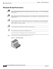
... Figure C-4). Figure C-4 Terminal Block Plug 60530 Catalyst 3550 Multilayer Switch Hardware Installation Guide C-4 OL-6155-01 Statement 1003 Caution You must comply with 5 A-branch-circuit protection. Note This installation must connect the Catalyst 3550-24-DC switch only to a DC-input power source that ...VDC. Caution The switch must be damaged. Connecting to DC Power Appendix C DC Power Connections Wiring the DC-Input Power Source Warning Only trained and qualified personnel should be allowed to install, replace, or service this range, the switch might not operate ...
... Figure C-4). Figure C-4 Terminal Block Plug 60530 Catalyst 3550 Multilayer Switch Hardware Installation Guide C-4 OL-6155-01 Statement 1003 Caution You must comply with 5 A-branch-circuit protection. Note This installation must connect the Catalyst 3550-24-DC switch only to a DC-input power source that ...VDC. Caution The switch must be damaged. Connecting to DC Power Appendix C DC Power Connections Wiring the DC-Input Power Source Warning Only trained and qualified personnel should be allowed to install, replace, or service this range, the switch might not operate ...