
Installation Guide
Page 29
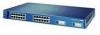
... address • SNMP Power Redundancy • Connection for optional Cisco RPS 600 that operates on all 10/100 ports • Support for fan-fault and over-temperature detection through Visual Switch Manager (VSM) Front-Panel Description The front panel of the Catalyst 3512, 3524, 3524-PWR and 3548 XL switches (Figure 1-3, Figure 1-4, Figure 1-5, and Figure 1-6) have a set of LEDs...
... address • SNMP Power Redundancy • Connection for optional Cisco RPS 600 that operates on all 10/100 ports • Support for fan-fault and over-temperature detection through Visual Switch Manager (VSM) Front-Panel Description The front panel of the Catalyst 3512, 3524, 3524-PWR and 3548 XL switches (Figure 1-3, Figure 1-4, Figure 1-5, and Figure 1-6) have a set of LEDs...

Installation Guide
Page 39
... The Cisco RPS 300 (model PWR300-AC-RPS) supports the Catalyst 3524-PWR XL switch. 78-6456-04 Catalyst 3500 Series XL Hardware Installation Guide 1-15 The switch goes through its normal boot sequence when it restarts. RPS is functioning properly. Note If you are both powered on page 1-23. If the switch power supply fails, the switch powers down , or a fan...
... The Cisco RPS 300 (model PWR300-AC-RPS) supports the Catalyst 3524-PWR XL switch. 78-6456-04 Catalyst 3500 Series XL Hardware Installation Guide 1-15 The switch goes through its normal boot sequence when it restarts. RPS is functioning properly. Note If you are both powered on page 1-23. If the switch power supply fails, the switch powers down , or a fan...

Installation Guide
Page 40
... and Table 1-8 explain how to the Cisco Redundant Power System 300 Hardware Installation Guide. RPS is backing up another switch in use by the switch. 1-16 Catalyst 3500 Series XL Hardware Installation Guide 78-6456-04 RPS is the default mode. The switch is down , or a fan on the RPS. The port modes (... current bandwidth in the stack. RPS is not installed. Front-Panel Description Chapter 1 Product Overview Table 1-5 RPS LED for the Catalyst 3524-PWR XL Switch Color Off Solid green Blinking green Solid amber Blinking amber RPS Status RPS is off or is connected and operational.
... and Table 1-8 explain how to the Cisco Redundant Power System 300 Hardware Installation Guide. RPS is backing up another switch in use by the switch. 1-16 Catalyst 3500 Series XL Hardware Installation Guide 78-6456-04 RPS is the default mode. The switch is down , or a fan on the RPS. The port modes (... current bandwidth in the stack. RPS is not installed. Front-Panel Description Chapter 1 Product Overview Table 1-5 RPS LED for the Catalyst 3524-PWR XL Switch Color Off Solid green Blinking green Solid amber Blinking amber RPS Status RPS is off or is connected and operational.

Installation Guide
Page 45
... Rear-Panel Description Rear-Panel Description Switch rear panels have an AC power connector, an RPS connector, and an RJ-45 console port (see Figure 1-17, Figure 1-19, Figure 1-18, and Figure 1-20), which are described in this section. Figure 1-17 Catalyst 3508G XL Rear Panel 18963 RATING 100-127....T+E3P.3OVW***E@R1S4UAP, PLY DC INPUT +12V***@3A AC power connector RJ-45 console port Redundant power system connector Figure 1-18 Catalyst 3512 and 3524 XL Rear Panel Fans 18964 RATING 100-127/200-240V~ 1.0A/0.5A 50-60HZ AC power connector 78-6456-04 CONSOLE DC INPUTS FOR REMOTE POWER...
... Rear-Panel Description Rear-Panel Description Switch rear panels have an AC power connector, an RPS connector, and an RJ-45 console port (see Figure 1-17, Figure 1-19, Figure 1-18, and Figure 1-20), which are described in this section. Figure 1-17 Catalyst 3508G XL Rear Panel 18963 RATING 100-127....T+E3P.3OVW***E@R1S4UAP, PLY DC INPUT +12V***@3A AC power connector RJ-45 console port Redundant power system connector Figure 1-18 Catalyst 3512 and 3524 XL Rear Panel Fans 18964 RATING 100-127/200-240V~ 1.0A/0.5A 50-60HZ AC power connector 78-6456-04 CONSOLE DC INPUTS FOR REMOTE POWER...

Installation Guide
Page 46
...Catalyst 3524-PWR XL Rear Panel RATING 100-127/200-240V~ 3.5A/1.8A 50-60HZ DC INPUTS FOR REMOTE POWER SUPPLY SPECIFIED IN MANUAL. -48V @3A, +12V @6A CONSOLE AC power connector Redundant power system connector RJ-45 console port Figure 1-20 Catalyst 3548 XL Rear Panel Chapter 1 Product Overview Fans... @1.1A CONSOLE AC power connector Fan exhaust RJ-45 console port Redundant power system connector Power Connectors You can provide power to the switch either through the internal power supply or through the Cisco RPS. 1-22 Catalyst 3500 Series XL Hardware Installation Guide 78-6456-04
...Catalyst 3524-PWR XL Rear Panel RATING 100-127/200-240V~ 3.5A/1.8A 50-60HZ DC INPUTS FOR REMOTE POWER SUPPLY SPECIFIED IN MANUAL. -48V @3A, +12V @6A CONSOLE AC power connector Redundant power system connector RJ-45 console port Figure 1-20 Catalyst 3548 XL Rear Panel Chapter 1 Product Overview Fans... @1.1A CONSOLE AC power connector Fan exhaust RJ-45 console port Redundant power system connector Power Connectors You can provide power to the switch either through the internal power supply or through the Cisco RPS. 1-22 Catalyst 3500 Series XL Hardware Installation Guide 78-6456-04

Installation Guide
Page 96
... to 45°C). - The Catalyst 3524-PWR XL switch can operate normally with one failed fan. Place the switch in an environment that is overheating. • Nonfatal or fatal POST error detected. Make sure the switch is connected to the LAN-to-phone jack on Improper cabling. Cisco IP Phone fails to check if a fan on the Catalyst 3524-PWR XL. Resolution • Either...
... to 45°C). - The Catalyst 3524-PWR XL switch can operate normally with one failed fan. Place the switch in an environment that is overheating. • Nonfatal or fatal POST error detected. Make sure the switch is connected to the LAN-to-phone jack on Improper cabling. Cisco IP Phone fails to check if a fan on the Catalyst 3524-PWR XL. Resolution • Either...