
Software Configuration Guide
Page 14
...Configuration 14-7 Default Ethernet VLAN Configuration 14-8 Creating or Modifying an Ethernet VLAN 14-8 Deleting a VLAN 14-10 Assigning Static-Access Ports to a VLAN 14-11 Configuring Extended-Range VLANs 14-12 Default VLAN Configuration 14-12 Extended-Range VLAN Configuration Guidelines 14-12 ...Using STP Port Priorities 14-21 Load Sharing Using STP Path Cost 14-23 Configuring VMPS 14-24 Understanding VMPS 14-25 Dynamic Port VLAN Membership 14-25 VMPS Database Configuration File 14-26 Default VMPS Configuration 14-27 VMPS Configuration Guidelines 14-28 Catalyst 2950 Desktop Switch Software ...
...Configuration 14-7 Default Ethernet VLAN Configuration 14-8 Creating or Modifying an Ethernet VLAN 14-8 Deleting a VLAN 14-10 Assigning Static-Access Ports to a VLAN 14-11 Configuring Extended-Range VLANs 14-12 Default VLAN Configuration 14-12 Extended-Range VLAN Configuration Guidelines 14-12 ...Using STP Port Priorities 14-21 Load Sharing Using STP Path Cost 14-23 Configuring VMPS 14-24 Understanding VMPS 14-25 Dynamic Port VLAN Membership 14-25 VMPS Database Configuration File 14-26 Default VMPS Configuration 14-27 VMPS Configuration Guidelines 14-28 Catalyst 2950 Desktop Switch Software ...

Software Configuration Guide
Page 16
Contents 17 C H A P T E R Default Voice VLAN Configuration 16-2 Voice VLAN Configuration Guidelines 16-3 Configuring a Port to Connect to a Cisco 7960 IP Phone 16-3 Configuring Ports to Carry Voice Traffic in 802.1Q Frames 16-4 Configuring Ports to Carry Voice Traffic in 802.1P Priority Tagged Frames 16-4 Overriding the CoS Priority of Incoming Data Frames 16...-21 Configuring IGMP Profiles 17-21 Applying IGMP Profiles 17-22 Setting the Maximum Number of IGMP Groups 17-23 Displaying IGMP Filtering Configuration 17-24 Catalyst 2950 Desktop Switch Software Configuration Guide xvi 78-14982-01
Contents 17 C H A P T E R Default Voice VLAN Configuration 16-2 Voice VLAN Configuration Guidelines 16-3 Configuring a Port to Connect to a Cisco 7960 IP Phone 16-3 Configuring Ports to Carry Voice Traffic in 802.1Q Frames 16-4 Configuring Ports to Carry Voice Traffic in 802.1P Priority Tagged Frames 16-4 Overriding the CoS Priority of Incoming Data Frames 16...-21 Configuring IGMP Profiles 17-21 Applying IGMP Profiles 17-22 Setting the Maximum Number of IGMP Groups 17-23 Displaying IGMP Filtering Configuration 17-24 Catalyst 2950 Desktop Switch Software Configuration Guide xvi 78-14982-01

Software Configuration Guide
Page 21
... Classifying, Policing, and Marking Traffic by Using Policy Maps 26-21 Configuring CoS Maps 26-24 Configuring the CoS-to-DSCP Map 26-25 Configuring the DSCP-to-CoS Map 26-26 ...-30 Configuring EtherChannels 27-1 Understanding EtherChannels 27-1 Understanding Port-Channel Interfaces 27-2 Understanding the Port Aggregation Protocol 27-3 PAgP Modes 27-4 Physical Learners and Aggregate-Port Learners 27-5 PAgP Interaction with Other Features 27-5 ...from a Lost or Forgotten Password 28-6 Recovering from a Command Switch Failure 28-8 Catalyst 2950 Desktop Switch Software Configuration Guide xxi
... Classifying, Policing, and Marking Traffic by Using Policy Maps 26-21 Configuring CoS Maps 26-24 Configuring the CoS-to-DSCP Map 26-25 Configuring the DSCP-to-CoS Map 26-26 ...-30 Configuring EtherChannels 27-1 Understanding EtherChannels 27-1 Understanding Port-Channel Interfaces 27-2 Understanding the Port Aggregation Protocol 27-3 PAgP Modes 27-4 Physical Learners and Aggregate-Port Learners 27-5 PAgP Interaction with Other Features 27-5 ...from a Lost or Forgotten Password 28-6 Recovering from a Command Switch Failure 28-8 Catalyst 2950 Desktop Switch Software Configuration Guide xxi
Software Configuration Guide
Page 27
...Switched Port Analyzer (SPAN) and Remote SPAN (RSPAN), which is running the per-VLAN spanning-tree (PVST) or the MSTP. Catalyst 2950 Desktop Switch Software Configuration Guide xxvii Chapter 9, "Configuring the Switch... STP," describes how to configure Cisco Discovery Protocol (CDP) on the switch. Chapter 23, "Configuring System Message...24, "Configuring SNMP," describes how to be created. RSTP provides rapid convergence, and MSTP enables VLANs to configure the Simple Network Management Protocol (SNMP). Preface 78-14982-01 Organization Chapter 8, "Configuring 802.1X Port...
...Switched Port Analyzer (SPAN) and Remote SPAN (RSPAN), which is running the per-VLAN spanning-tree (PVST) or the MSTP. Catalyst 2950 Desktop Switch Software Configuration Guide xxvii Chapter 9, "Configuring the Switch... STP," describes how to configure Cisco Discovery Protocol (CDP) on the switch. Chapter 23, "Configuring System Message...24, "Configuring SNMP," describes how to be created. RSTP provides rapid convergence, and MSTP enables VLANs to configure the Simple Network Management Protocol (SNMP). Preface 78-14982-01 Organization Chapter 8, "Configuring 802.1X Port...
Software Configuration Guide
Page 35
...this switch. 78-14982-01 Catalyst 2950 Desktop Switch Software Configuration Guide 1-3 Extended discovery of Using CMS and Clustering Switches" section on page 1-7. Refer to the command switch. • Hot Standby Router Protocol (HSRP) for command-switch redundancy. Automatic discovery of candidate switches and...to 1530 bytes • Per-port broadcast storm control for preventing faulty end stations from 1500 to ensure retrieval of eligible cluster members). - The Catalyst 2950G-12-EI, 2950G-24-EI, 2950G-24-EI-DC, and 2950G-48-EI switches running Cisco IOS Release 12.1(6)EA2 or ...
...this switch. 78-14982-01 Catalyst 2950 Desktop Switch Software Configuration Guide 1-3 Extended discovery of Using CMS and Clustering Switches" section on page 1-7. Refer to the command switch. • Hot Standby Router Protocol (HSRP) for command-switch redundancy. Automatic discovery of candidate switches and...to 1530 bytes • Per-port broadcast storm control for preventing faulty end stations from 1500 to ensure retrieval of eligible cluster members). - The Catalyst 2950G-12-EI, 2950G-24-EI, 2950G-24-EI-DC, and 2950G-48-EI switches running Cisco IOS Release 12.1(6)EA2 or ...
Software Configuration Guide
Page 37
...only with appropriate network resources, traffic patterns, and bandwidth Note The Catalyst 2950-12, Catalyst 2950-24, and Catalyst 2950SX-24 switches support only 64 port-based VLANs. • The switch supports up to 64 spanning-tree instances. and network security by...port-based authentication to prevent unauthorized devices from Cisco IP Phones Security • Bridge protocol data unit (BPDU) guard for shutting down a Port Fast-configured port when an invalid configuration occurs • Protected port option for restricting the forwarding of traffic to designated ports on the same switch...
...only with appropriate network resources, traffic patterns, and bandwidth Note The Catalyst 2950-12, Catalyst 2950-24, and Catalyst 2950SX-24 switches support only 64 port-based VLANs. • The switch supports up to 64 spanning-tree instances. and network security by...port-based authentication to prevent unauthorized devices from Cisco IP Phones Security • Bridge protocol data unit (BPDU) guard for shutting down a Port Fast-configured port when an invalid configuration occurs • Protected port option for restricting the forwarding of traffic to designated ports on the same switch...
Software Configuration Guide
Page 39
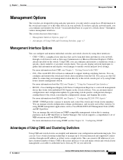
...is the easiest interface to use Cisco switch clustering technology to manage up to 16 interconnected and supported Catalyst switches through one IP address as CiscoWorks2000 LAN Management Suite (LMS) and HP OpenView. For more information about the CLI, see the Chapter 24, "Configuring SNMP." You can...management station that works with embedded CNS Agents in your management station directly to the switch console port or by connecting your network. You can configure and monitor the switch-on the switch. If you have a limited number of MIB extensions and four RMON groups. ...
...is the easiest interface to use Cisco switch clustering technology to manage up to 16 interconnected and supported Catalyst switches through one IP address as CiscoWorks2000 LAN Management Suite (LMS) and HP OpenView. For more information about the CLI, see the Chapter 24, "Configuring SNMP." You can...management station that works with embedded CNS Agents in your management station directly to the switch console port or by connecting your network. You can configure and monitor the switch-on the switch. If you have a limited number of MIB extensions and four RMON groups. ...
Software Configuration Guide
Page 71
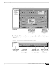
... a cluster- Right-click the command switch image to select multiple ports. Figure 3-4 Front Panel View from a Standalone 2950 LRE Switch 2950-24 2950-24 86459 Left-click the Mode button to change system-related settings. LEDs display the current port mode and the status of the port LED reflects port or link status. 78-14982-01 Catalyst 2950 Desktop Switch Software Configuration Guide 3-5 related...
... a cluster- Right-click the command switch image to select multiple ports. Figure 3-4 Front Panel View from a Standalone 2950 LRE Switch 2950-24 2950-24 86459 Left-click the Mode button to change system-related settings. LEDs display the current port mode and the status of the port LED reflects port or link status. 78-14982-01 Catalyst 2950 Desktop Switch Software Configuration Guide 3-5 related...
Software Configuration Guide
Page 72
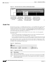
... the corresponding front-panel image. The front-panel image is receiving power from a 2950 non-LRE Standalone Switch 2950-24 2950-24 Left-click the Mode LEDs display the Right-click a port to button to select multiple ports. To deselect an icon or image, press the Ctrl key, and left -click...; To select a front-panel image, click either the cluster-tree icon or the corresponding front-panel image. Catalyst 2950 Desktop Switch Software Configuration Guide 3-6 78-14982-01 Switch is not powered up the meaning of the and the status of its members. The sequence of the cluster-tree...
... the corresponding front-panel image. The front-panel image is receiving power from a 2950 non-LRE Standalone Switch 2950-24 2950-24 Left-click the Mode LEDs display the Right-click a port to button to select multiple ports. To deselect an icon or image, press the Ctrl key, and left -click...; To select a front-panel image, click either the cluster-tree icon or the corresponding front-panel image. Catalyst 2950 Desktop Switch Software Configuration Guide 3-6 78-14982-01 Switch is not powered up the meaning of the and the status of its members. The sequence of the cluster-tree...
Software Configuration Guide
Page 150
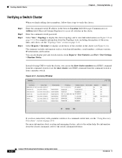
....10.2 10.10.10.3 12.1(6)EA2 10.10.10.9 13.0(5)XU If you can also display port and switch statistics from a member switch. For information about creating and managing clusters, refer to the switch command reference. 65727 6-24 Catalyst 2950 Desktop Switch Software Configuration Guide 78-14982-01 Select Reports > Inventory to display an inventory of using CMS...
....10.2 10.10.10.3 12.1(6)EA2 10.10.10.9 13.0(5)XU If you can also display port and switch statistics from a member switch. For information about creating and managing clusters, refer to the switch command reference. 65727 6-24 Catalyst 2950 Desktop Switch Software Configuration Guide 78-14982-01 Select Reports > Inventory to display an inventory of using CMS...

Software Configuration Guide
Page 235
... 0/1 and 0/2: Switch# configure terminal Switch(config)# interface range fastethernet0/1 - 3, gigabitethernet0/1 - 2 Switch(config-if-range)# no shutdown Switch(config-if-range)# *Oct 6 08:24:35: %LINK-3-UPDOWN: Interface FastEthernet0/1, changed state to up *Oct 6 08:24:35: %LINK-3-...port} - {last port}, where slot is entered. Wait until the command prompt reappears before exiting interface-range configuration mode. 78-14982-01 Catalyst 2950 Desktop Switch Software Configuration Guide 9-7 Chapter 9 Configuring the Switch Interfaces Using the Interface Command - port-channel port...
... 0/1 and 0/2: Switch# configure terminal Switch(config)# interface range fastethernet0/1 - 3, gigabitethernet0/1 - 2 Switch(config-if-range)# no shutdown Switch(config-if-range)# *Oct 6 08:24:35: %LINK-3-UPDOWN: Interface FastEthernet0/1, changed state to up *Oct 6 08:24:35: %LINK-3-...port} - {last port}, where slot is entered. Wait until the command prompt reappears before exiting interface-range configuration mode. 78-14982-01 Catalyst 2950 Desktop Switch Software Configuration Guide 9-7 Chapter 9 Configuring the Switch Interfaces Using the Interface Command - port-channel port...

Software Configuration Guide
Page 245
... VLAN: dot1p (Inactive) Appliance trust: 5 Name: Fa0/2 Switchport: Enabled Administrative Mode: static access 78-14982-01 Catalyst 2950 Desktop Switch Software Configuration Guide 9-17 Display interface status or a list of all interfaces and the interface status. Display the description ...24 Gi0/1 Gi0/2 notconnect 1 notconnect 1 notconnect 1 notconnect 1 auto auto auto auto auto 10/100BaseTX auto 10/100BaseTX auto unknown auto unknown This example shows how to display the status of interfaces in RAM for the interface. Display the usability status of switching (nonrouting) ports...
... VLAN: dot1p (Inactive) Appliance trust: 5 Name: Fa0/2 Switchport: Enabled Administrative Mode: static access 78-14982-01 Catalyst 2950 Desktop Switch Software Configuration Guide 9-17 Display interface status or a list of all interfaces and the interface status. Display the description ...24 Gi0/1 Gi0/2 notconnect 1 notconnect 1 notconnect 1 notconnect 1 auto auto auto auto auto 10/100BaseTX auto 10/100BaseTX auto unknown auto unknown This example shows how to display the status of interfaces in RAM for the interface. Display the usability status of switching (nonrouting) ports...
Software Configuration Guide
Page 254
Configuring LRE Ports Chapter 10 Configuring LRE Environmental Guidelines for LRE Links The guidelines for your LRE environment are based on these factors: • Maximum distance between 25-pair bundles and larger bundles. - Where the wiring between the LRE switch and CPE device leaves the building (or the armored conduits certified for indoor... or 20 AWG) with local regulations for the details of this estimate, assume that the wiring conforms to maximize the performance of all connections. 10-6 Catalyst 2950 Desktop Switch Software Configuration Guide 78-14982-01
Configuring LRE Ports Chapter 10 Configuring LRE Environmental Guidelines for LRE Links The guidelines for your LRE environment are based on these factors: • Maximum distance between 25-pair bundles and larger bundles. - Where the wiring between the LRE switch and CPE device leaves the building (or the armored conduits certified for indoor... or 20 AWG) with local regulations for the details of this estimate, assume that the wiring conforms to maximize the performance of all connections. 10-6 Catalyst 2950 Desktop Switch Software Configuration Guide 78-14982-01

Software Configuration Guide
Page 260
...the environment. Table 10-3 lists the SNR requirements for downstream rates for different profiles. 10-12 Catalyst 2950 Desktop Switch Software Configuration Guide 78-14982-01 You can cause the system to choose a lower profile, which ...35 33 35 33 35 15 17 15 17 15 17 High Noise SNR 26 26 32 24 32 39 32 32 32 39 39 39 39 39 20 20 20 Table 10-4 lists...; The switch does not guarantee any internal mechanism to provide a stable link. margins are only guaranteed only when the link is not established. The link has to the required SNR. Configuring LRE Ports Chapter 10...
...the environment. Table 10-3 lists the SNR requirements for downstream rates for different profiles. 10-12 Catalyst 2950 Desktop Switch Software Configuration Guide 78-14982-01 You can cause the system to choose a lower profile, which ...35 33 35 33 35 15 17 15 17 15 17 High Noise SNR 26 26 32 24 32 39 32 32 32 39 39 39 39 39 20 20 20 Table 10-4 lists...; The switch does not guarantee any internal mechanism to provide a stable link. margins are only guaranteed only when the link is not established. The link has to the required SNR. Configuring LRE Ports Chapter 10...
Software Configuration Guide
Page 337
...; Configuring VLAN Trunks, page 14-15 • Configuring VMPS, page 14-24 Understanding VLANs A VLAN is a switched network that do not belong to maintain global VLAN configuration for your network. ... are not physically located on VTP, see Chapter 15, "Configuring VTP." 78-14982-01 Catalyst 2950 Desktop Switch Software Configuration Guide 14-1 See Chapter 11, "Configuring STP" and Chapter 12, "Configuring RSTP...includes information about VLAN modes and the VLAN Membership Policy Server (VMPS). Any switch port can group end stations even if they are forwarded and flooded only to the ...
...; Configuring VLAN Trunks, page 14-15 • Configuring VMPS, page 14-24 Understanding VLANs A VLAN is a switched network that do not belong to maintain global VLAN configuration for your network. ... are not physically located on VTP, see Chapter 15, "Configuring VTP." 78-14982-01 Catalyst 2950 Desktop Switch Software Configuration Guide 14-1 See Chapter 11, "Configuring STP" and Chapter 12, "Configuring RSTP...includes information about VLAN modes and the VLAN Membership Policy Server (VMPS). Any switch port can group end stations even if they are forwarded and flooded only to the ...
Software Configuration Guide
Page 359
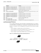
... 18 Step 19 Step 20 Step 21 Command spanning-tree vlan 8 port-priority 10 spanning-tree vlan 9 port-priority 10 spanning-tree vlan 10 port-priority 10 exit interface fastethernet0/2 Step 22 Step 23 Step 24 Step 25 Step 26 Step 27 Step 28 spanning-tree vlan... Trunk port 1 of 19. • VLANs 8 through 10 are 100BASE-T ports. Return to share VLAN traffic by Path Cost Switch 1 Trunk port 1 VLANs 2 - 4 (path cost 30) VLANs 8 - 10 (path cost 19) Trunk port 2 VLANs 8 - 10 (path cost 30) VLANs 2 - 4 (path cost 19) 16591 Switch 2 78-14982-01 Catalyst 2950 Desktop Switch Software ...
... 18 Step 19 Step 20 Step 21 Command spanning-tree vlan 8 port-priority 10 spanning-tree vlan 9 port-priority 10 spanning-tree vlan 10 port-priority 10 exit interface fastethernet0/2 Step 22 Step 23 Step 24 Step 25 Step 26 Step 27 Step 28 spanning-tree vlan... Trunk port 1 of 19. • VLANs 8 through 10 are 100BASE-T ports. Return to share VLAN traffic by Path Cost Switch 1 Trunk port 1 VLANs 2 - 4 (path cost 30) VLANs 8 - 10 (path cost 19) Trunk port 2 VLANs 8 - 10 (path cost 30) VLANs 2 - 4 (path cost 19) 16591 Switch 2 78-14982-01 Catalyst 2950 Desktop Switch Software ...
Software Configuration Guide
Page 360
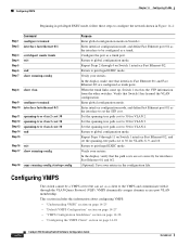
... 14-28 • "Configuring the VMPS Client" section on Switch 1. Repeat Steps 2 through 11 on Switch 1 interface Fast Ethernet 0/2. In the display, verify that the path costs are configured as trunk ports. Configuring VMPS The switch cannot be configured as a client to the VMPS and communicate ...Step 17 show running-config Step 18 copy running-config startup-config Purpose Enter global configuration mode on page 14-28 14-24 Catalyst 2950 Desktop Switch Software Configuration Guide 78-14982-01 Verify your entries. Set the spanning-tree path cost to 30 for VLAN 2. Return...
... 14-28 • "Configuring the VMPS Client" section on Switch 1. Repeat Steps 2 through 11 on Switch 1 interface Fast Ethernet 0/2. In the display, verify that the path costs are configured as trunk ports. Configuring VMPS The switch cannot be configured as a client to the VMPS and communicate ...Step 17 show running-config Step 18 copy running-config startup-config Purpose Enter global configuration mode on page 14-28 14-24 Catalyst 2950 Desktop Switch Software Configuration Guide 78-14982-01 Verify your entries. Set the spanning-tree path cost to 30 for VLAN 2. Return...

Software Configuration Guide
Page 486
... commands use the word traps in the configuration file. Table 24-4 Switch Notification Types Notification Type Keyword c2900 cluster config entity Description Generates a trap for SNMP entity changes. 24-10 Catalyst 2950 Desktop Switch Software Configuration Guide 78-14982-01 The default is defined, ...option in encrypted format. • (Optional) Enter access access-list with the optional UDP port number. Generates a trap for SNMP configuration changes. Traps are sent. Switches running -config startup-config Purpose Configure a new user to an SNMP group. • The...
... commands use the word traps in the configuration file. Table 24-4 Switch Notification Types Notification Type Keyword c2900 cluster config entity Description Generates a trap for SNMP entity changes. 24-10 Catalyst 2950 Desktop Switch Software Configuration Guide 78-14982-01 The default is defined, ...option in encrypted format. • (Optional) Enter access access-list with the optional UDP port number. Generates a trap for SNMP configuration changes. Traps are sent. Switches running -config startup-config Purpose Configure a new user to an SNMP group. • The...

Software Configuration Guide
Page 487
...global configuration mode. Generates a trap for SNMP VLAN membership changes. Sends Cisco enterprise-specific notifications when a Transmission Control Protocol (TCP) connection closes. snmp-server user username groupname remote host [udp-port port] {v1 | v2c | v3 [auth {md5 | sha} auth-...read readview] [write writeview] [notify notifyview] [access access-list] Configure an SNMP group. 78-14982-01 Catalyst 2950 Desktop Switch Software Configuration Guide 24-11 If you receive an error message, and the command is not executed. Generates a trap for MAC address notifications....
...global configuration mode. Generates a trap for SNMP VLAN membership changes. Sends Cisco enterprise-specific notifications when a Transmission Control Protocol (TCP) connection closes. snmp-server user username groupname remote host [udp-port port] {v1 | v2c | v3 [auth {md5 | sha} auth-...read readview] [write writeview] [notify notifyview] [access access-list] Configure an SNMP group. 78-14982-01 Catalyst 2950 Desktop Switch Software Configuration Guide 24-11 If you receive an error message, and the command is not executed. Generates a trap for MAC address notifications....
Software Configuration Guide
Page 642
...addresses, affect of 11-8 overview 11-2 path costs 14-23, 14-24 Port Fast described 13-2 enabling 13-14 port priorities 14-22 preventing root switch selection 13-12 IN-26 Catalyst 2950 Desktop Switch Software Configuration Guide redundant connectivity 11-8 root guard described 13-12 enabling 13...-19 root port, defined 11-3 root switch affects of extended system ID 11-4, ...
...addresses, affect of 11-8 overview 11-2 path costs 14-23, 14-24 Port Fast described 13-2 enabling 13-14 port priorities 14-22 preventing root switch selection 13-12 IN-26 Catalyst 2950 Desktop Switch Software Configuration Guide redundant connectivity 11-8 root guard described 13-12 enabling 13...-19 root port, defined 11-3 root switch affects of extended system ID 11-4, ...


