Hardware Installation Guide
Page 2
...UCB's public domain version of California. CCSP, the Cisco Square Bridge logo, Cisco Unity, Follow Me Browsing, FormShare, and StackWise are service marks of their own expense. THE SPECIFICATIONS AND INFORMATION REGARDING THE PRODUCTS IN THIS MANUAL ARE ... company. (0406R) Catalyst 2950 Switch Hardware Installation Guide Copyright © 2004 Cisco Systems, Inc. and Aironet, ASIST, BPX, Catalyst, CCDA, CCDP, CCIE, CCIP, CCNA, CCNP, Cisco, the Cisco Certified Internetwork Expert logo, Cisco IOS, Cisco Press, Cisco Systems, Cisco Systems Capital, the Cisco Systems logo, Empowering the...
...UCB's public domain version of California. CCSP, the Cisco Square Bridge logo, Cisco Unity, Follow Me Browsing, FormShare, and StackWise are service marks of their own expense. THE SPECIFICATIONS AND INFORMATION REGARDING THE PRODUCTS IN THIS MANUAL ARE ... company. (0406R) Catalyst 2950 Switch Hardware Installation Guide Copyright © 2004 Cisco Systems, Inc. and Aironet, ASIST, BPX, Catalyst, CCDA, CCDP, CCIE, CCIP, CCNA, CCNP, Cisco, the Cisco Certified Internetwork Expert logo, Cisco IOS, Cisco Press, Cisco Systems, Cisco Systems Capital, the Cisco Systems logo, Empowering the...

Hardware Installation Guide
Page 5
... 1000BASE-T SFP Modules 2-39 Where to Go Next 2-40 Troubleshooting 3-1 Understanding POST Results 3-1 Diagnosing Problems 3-1 Technical Specifications A-1 Connectors and Cables B-1 Connector Specifications B-1 10/100 Ports B-1 10/100/1000 Ports B-2 Connecting to 10BASE-T and 100BASE-TX Devices B-2 Connecting to ... Module Ports B-4 GigaStack GBIC Module Ports B-4 SFP Module Ports B-5 Console Port B-5 Identifying a Crossover Cable B-5 Cable and Adapter Specifications B-6 Two Twisted-Pair Cable Pinouts B-6 Four Twisted-Pair Cable Pinouts for 10/100 Ports B-7 Four Twisted-Pair Cable Pinouts for ...
... 1000BASE-T SFP Modules 2-39 Where to Go Next 2-40 Troubleshooting 3-1 Understanding POST Results 3-1 Diagnosing Problems 3-1 Technical Specifications A-1 Connectors and Cables B-1 Connector Specifications B-1 10/100 Ports B-1 10/100/1000 Ports B-2 Connecting to 10BASE-T and 100BASE-TX Devices B-2 Connecting to ... Module Ports B-4 GigaStack GBIC Module Ports B-4 SFP Module Ports B-5 Console Port B-5 Identifying a Crossover Cable B-5 Cable and Adapter Specifications B-6 Two Twisted-Pair Cable Pinouts B-6 Four Twisted-Pair Cable Pinouts for 10/100 Ports B-7 Four Twisted-Pair Cable Pinouts for ...

Hardware Installation Guide
Page 9
...been created or changed for installing a Catalyst 2950 switch, hereafter referred to install a switch, and provides troubleshooting information and specifications. For more information, see the switch software configuration guide, the switch system message guide, and the switch command reference. It also does not ... helpful suggestions or references to configure software features on your switch or describe the Catalyst 2950-specific system messages that you are in this manual. OL-6156-01 Catalyst 2950 Switch Hardware Installation Guide ix Preface Audience This guide is for...
...been created or changed for installing a Catalyst 2950 switch, hereafter referred to install a switch, and provides troubleshooting information and specifications. For more information, see the switch software configuration guide, the switch system message guide, and the switch command reference. It also does not ... helpful suggestions or references to configure software features on your switch or describe the Catalyst 2950-specific system messages that you are in this manual. OL-6156-01 Catalyst 2950 Switch Hardware Installation Guide ix Preface Audience This guide is for...

Hardware Installation Guide
Page 31
... and are field-replaceable. These transceiver modules are labeled Uplink Port 1 and Uplink Port 2. OL-6156-01 Catalyst 2950 Switch Hardware Installation Guide 1-11 The Catalyst 2950 LRE switch has four physical input ports that scenario, whichever media type establishes a link first has precedence over the 10/... end of the cable, and for reliable communications, the cable must match the wave-length specifications on Uplink Port 1. If you can connect to both, in the Catalyst 2950 LRE switch release notes. For example, you connect to either the SFP module port or the 10/...
... and are field-replaceable. These transceiver modules are labeled Uplink Port 1 and Uplink Port 2. OL-6156-01 Catalyst 2950 Switch Hardware Installation Guide 1-11 The Catalyst 2950 LRE switch has four physical input ports that scenario, whichever media type establishes a link first has precedence over the 10/... end of the cable, and for reliable communications, the cable must match the wave-length specifications on Uplink Port 1. If you can connect to both, in the Catalyst 2950 LRE switch release notes. For example, you connect to either the SFP module port or the 10/...

Hardware Installation Guide
Page 32
... modules, see your SFP module documentation. 1-12 Catalyst 2950 Switch Hardware Installation Guide OL-6156-01 the distance depends on the Catalyst 2950 LRE switch. Use only Cisco-approved SFP modules on the fiber quality, the ...Cisco-approved SFP modules have a serial EEPROM that contains the module serial number, the vendor name and ID, a unique security code, and cyclic redundancy check (CRC). A mode-conditioning patch cord is inserted in an elevated bit error rate (BER). Front-Panel Description Chapter 1 Overview Table 1-2 Fiber-Optic SFP Module Port Cabling Specifications...
... modules, see your SFP module documentation. 1-12 Catalyst 2950 Switch Hardware Installation Guide OL-6156-01 the distance depends on the Catalyst 2950 LRE switch. Use only Cisco-approved SFP modules on the fiber quality, the ...Cisco-approved SFP modules have a serial EEPROM that contains the module serial number, the vendor name and ID, a unique security code, and cyclic redundancy check (CRC). A mode-conditioning patch cord is inserted in an elevated bit error rate (BER). Front-Panel Description Chapter 1 Overview Table 1-2 Fiber-Optic SFP Module Port Cabling Specifications...

Hardware Installation Guide
Page 43
...V and 12 V with a total maximum output power of 675 W. Cisco RPS Connector Specific Cisco RPS models support specific Catalyst 2950 switches: • Cisco RPS 300 (model PWR300-AC-RPS-N1) • Cisco RPS 675 (model PWR675-AC-RPS-N1=) Cisco RPS 300 The Cisco RPS 300 has two output levels: -48 V and 12 V with...8226; CAB-NP1200-AC-US= DC Power Connector The Catalyst 2950G-24-EI-DC and Catalyst 2950ST-24 LRE 997 switches have an internal DC-power converter. Caution You must connect the Catalyst 2950G-24-EI-DC and 2950ST-24 LRE 997 switches only to a DC-input power source that device, ...
...V and 12 V with a total maximum output power of 675 W. Cisco RPS Connector Specific Cisco RPS models support specific Catalyst 2950 switches: • Cisco RPS 300 (model PWR300-AC-RPS-N1) • Cisco RPS 675 (model PWR675-AC-RPS-N1=) Cisco RPS 300 The Cisco RPS 300 has two output levels: -48 V and 12 V with...8226; CAB-NP1200-AC-US= DC Power Connector The Catalyst 2950G-24-EI-DC and Catalyst 2950ST-24 LRE 997 switches have an internal DC-power converter. Caution You must connect the Catalyst 2950G-24-EI-DC and 2950ST-24 LRE 997 switches only to a DC-input power source that device, ...
Hardware Installation Guide
Page 44
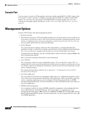
... Adapter Specifications" section on the switch. The device manager page appears. Management Options Chapter 1 Overview Console Port You can connect a switch to a PC through a web browser. To launch the Device Manager, enter the switch IP address in your SNMP application. 1-24 Catalyst 2950 Switch Hardware ...console-port and adapter-pinout information, see the documentation that you can order a kit (part number ACS-DSBUASYN=) with Cisco Network Assistant guide and the Network Assistant online help for more information, see the Getting Started with that came with your ...
... Adapter Specifications" section on the switch. The device manager page appears. Management Options Chapter 1 Overview Console Port You can connect a switch to a PC through a web browser. To launch the Device Manager, enter the switch IP address in your SNMP application. 1-24 Catalyst 2950 Switch Hardware ...console-port and adapter-pinout information, see the documentation that you can order a kit (part number ACS-DSBUASYN=) with Cisco Network Assistant guide and the Network Assistant online help for more information, see the Getting Started with that came with your ...

Hardware Installation Guide
Page 45
... Configuration Registrar is a network management device that came with embedded Cisco Networking Services (CNS) agents in the switch software. OL-6156-01 Catalyst 2950 Switch Hardware Installation Guide 1-25 You can automate initial configurations and configuration updates by generating switch-specific configuration changes, sending them to the switch, executing the configuration change, and logging the results. For...
... Configuration Registrar is a network management device that came with embedded Cisco Networking Services (CNS) agents in the switch software. OL-6156-01 Catalyst 2950 Switch Hardware Installation Guide 1-25 You can automate initial configurations and configuration updates by generating switch-specific configuration changes, sending them to the switch, executing the configuration change, and logging the results. For...

Hardware Installation Guide
Page 50
... Warning An exposed wire lead from the DC circuit. Catalyst 2950 Switch Hardware Installation Guide 2-4 OL-6156-01 Statement 171 Warning Before connecting or disconnecting ground or power wires to the OFF position, and tape the switch handle of security. Be sure that no exposed portion..., the cable length from the terminal block plug. For specific cable lengths, see the CWDM GBIC module documentation. A restricted access area can conduct harmful levels of the DC-input power source wire extends from a switch to be shielded when used in restricted access areas. Preparing...
... Warning An exposed wire lead from the DC circuit. Catalyst 2950 Switch Hardware Installation Guide 2-4 OL-6156-01 Statement 171 Warning Before connecting or disconnecting ground or power wires to the OFF position, and tape the switch handle of security. Be sure that no exposed portion..., the cable length from the terminal block plug. For specific cable lengths, see the CWDM GBIC module documentation. A restricted access area can conduct harmful levels of the DC-input power source wire extends from a switch to be shielded when used in restricted access areas. Preparing...

Hardware Installation Guide
Page 51
.... - Two 19-inch or 24-inch rack-mounting brackets OL-6156-01 Catalyst 2950 Switch Hardware Installation Guide 2-5 Note If the switch is installed in Appendix A, "Technical Specifications." • Clearance to ports is shipped with these items: • Catalyst 2950 Switch Getting Started Guide • Regulatory...; Cabling is missing or damaged, contact your Cisco representative or reseller for support. Return all 10/100 and 10/100/1000 ports must be connected with the Catalyst 2950G-24-EI-DC switch or the Catalyst 2950ST-24 LRE 997 switch) • Console cable • Mounting kit...
.... - Two 19-inch or 24-inch rack-mounting brackets OL-6156-01 Catalyst 2950 Switch Hardware Installation Guide 2-5 Note If the switch is installed in Appendix A, "Technical Specifications." • Clearance to ports is shipped with these items: • Catalyst 2950 Switch Getting Started Guide • Regulatory...; Cabling is missing or damaged, contact your Cisco representative or reseller for support. Return all 10/100 and 10/100/1000 ports must be connected with the Catalyst 2950G-24-EI-DC switch or the Catalyst 2950ST-24 LRE 997 switch) • Console cable • Mounting kit...
Hardware Installation Guide
Page 69
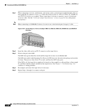
...requirements for reliable communications, the cable must match the wave-length specifications on the front of the potential damage to the cables, the cable connector, or the optical interfaces in a Switch Metal flap door 1 Catalyst 2950 SERIES 2 74533 GigaStack GBIC module GBIC module slot Installing ...useful life. Determine which type of the cable, and for the switch. Use only Cisco SFP modules on installing, removing, and cabling the SFP module, refer to it because of the Catalyst 2950 LRE switches. Installing SFP Modules into SFP module slots on the other end of...
...requirements for reliable communications, the cable must match the wave-length specifications on the front of the potential damage to the cables, the cable connector, or the optical interfaces in a Switch Metal flap door 1 Catalyst 2950 SERIES 2 74533 GigaStack GBIC module GBIC module slot Installing ...useful life. Determine which type of the cable, and for the switch. Use only Cisco SFP modules on installing, removing, and cabling the SFP module, refer to it because of the Catalyst 2950 LRE switches. Installing SFP Modules into SFP module slots on the other end of...
Hardware Installation Guide
Page 74
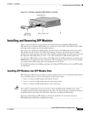
... 1 When connecting to connect each port. 2-28 Catalyst 2950 Switch Hardware Installation Guide OL-6156-01 Figure 2-35 shows the Catalyst 2950-12, 2950-24, 2950C-24, 2950SX-24, and 2950T-24 switch as an example. When connecting to switches or repeaters, insert a twisted-pair crossover cable. (See the "Cable and Adapter Specifications" section on page B-6 for solutions to cabling problems...
... 1 When connecting to connect each port. 2-28 Catalyst 2950 Switch Hardware Installation Guide OL-6156-01 Figure 2-35 shows the Catalyst 2950-12, 2950-24, 2950C-24, 2950SX-24, and 2950T-24 switch as an example. When connecting to switches or repeaters, insert a twisted-pair crossover cable. (See the "Cable and Adapter Specifications" section on page B-6 for solutions to cabling problems...
Hardware Installation Guide
Page 77
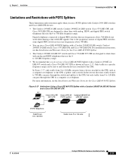
... 700 kHz do not use a Cisco LRE 48 POTS Splitter with a Catalyst 2950ST-24 LRE 997 switch and a Cisco 576 LRE 997 CPE as a computer or telephone, to the CPE. In the reverse direction, traffic from a device attached to the CPE, such as shown in a specific frequency range can pass from 0... to 700 kHz can pass through the CPE to 700 kHz frequency range. For installation instructions, see the Installation and Warranty Notes for the Cisco LRE 48 POTS Splitter. • The Catalyst 2950ST-24 LRE 997 switch and Cisco 576 LRE 997 CPE...
... 700 kHz do not use a Cisco LRE 48 POTS Splitter with a Catalyst 2950ST-24 LRE 997 switch and a Cisco 576 LRE 997 CPE as a computer or telephone, to the CPE. In the reverse direction, traffic from a device attached to the CPE, such as shown in a specific frequency range can pass from 0... to 700 kHz can pass through the CPE to 700 kHz frequency range. For installation instructions, see the Installation and Warranty Notes for the Cisco LRE 48 POTS Splitter. • The Catalyst 2950ST-24 LRE 997 switch and Cisco 576 LRE 997 CPE...

Hardware Installation Guide
Page 89
... recognizing an SFP module. If the fan has failed, call Cisco Systems. • Use the show post privileged EXEC command to see the switch software configuration guide. • Check if the fan has failed by... at both ends. • A crossover cable was used when a straight-through cables, see the "Cable and Adapter Specifications" section on the management console. Corrupted software. • Internal fan fault detected. • Nonfatal or fatal POST error... Symptom No connectivity. Possible Cause Incorrect or bad cable. OL-6156-01 Catalyst 2950 Switch Hardware Installation Guide 3-3
... recognizing an SFP module. If the fan has failed, call Cisco Systems. • Use the show post privileged EXEC command to see the switch software configuration guide. • Check if the fan has failed by... at both ends. • A crossover cable was used when a straight-through cables, see the "Cable and Adapter Specifications" section on the management console. Corrupted software. • Internal fan fault detected. • Nonfatal or fatal POST error... Symptom No connectivity. Possible Cause Incorrect or bad cable. OL-6156-01 Catalyst 2950 Switch Hardware Installation Guide 3-3

Hardware Installation Guide
Page 91
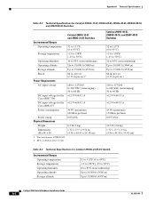
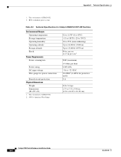
Table A-1 Technical Specifications for Catalyst 2950-12, 2950-24, 2950C-24, 2950SX-24, and 2950T-24 Switches Environmental Ranges Operating temperature 32 to 113°F (0 to 45°C) Storage temperature -13 to ... D) 1.72 x 17.5 x 9.52 in . This switch meets ASTM D3332. 2. A A P P E N D I X Technical Specifications OL-6156-01 Table A-1 through Table A-5 list the technical specifications for the switches other than the Catalyst 2950 Long-Reach Ethernet (LRE) switches. Table A-6 lists the technical specifications for the Cisco RPS2 300 Redundant Power System 100 to 127/200 to 240...
Table A-1 Technical Specifications for Catalyst 2950-12, 2950-24, 2950C-24, 2950SX-24, and 2950T-24 Switches Environmental Ranges Operating temperature 32 to 113°F (0 to 45°C) Storage temperature -13 to ... D) 1.72 x 17.5 x 9.52 in . This switch meets ASTM D3332. 2. A A P P E N D I X Technical Specifications OL-6156-01 Table A-1 through Table A-5 list the technical specifications for the switches other than the Catalyst 2950 Long-Reach Ethernet (LRE) switches. Table A-6 lists the technical specifications for the Cisco RPS2 300 Redundant Power System 100 to 127/200 to 240...
Hardware Installation Guide
Page 92
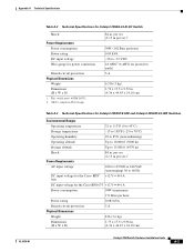
...input voltage 100 to 127/200 to 240 VAC (autoranging) 50 to 60 Hz DC input voltage for the +12 V @4.5 A Cisco RPS2 300 DC input voltage for the +12 V @4.5 A Cisco RPS 675 Power consumption 30 W (maximum) 102 Btus per hour 0.075 kVA 10.5 lb (4.8 kg) 1.72 x 17.5 x... 6.5 lb (3 kg) Dimensions (H x W x D) 1.72 x 17.5 x 9.52 in . (4.36 x 44.45 x 33.02 cm) Table A-3 Technical Specifications for Catalyst 2950G-24-EI-DC Switch Environmental Ranges Operating temperature Storage temperature Operating humidity Operating altitude Storage altitude 32 to 113°F (0 to 45°C) -13 to 158°...
...input voltage 100 to 127/200 to 240 VAC (autoranging) 50 to 60 Hz DC input voltage for the +12 V @4.5 A Cisco RPS2 300 DC input voltage for the +12 V @4.5 A Cisco RPS 675 Power consumption 30 W (maximum) 102 Btus per hour 0.075 kVA 10.5 lb (4.8 kg) 1.72 x 17.5 x... 6.5 lb (3 kg) Dimensions (H x W x D) 1.72 x 17.5 x 9.52 in . (4.36 x 44.45 x 33.02 cm) Table A-3 Technical Specifications for Catalyst 2950G-24-EI-DC Switch Environmental Ranges Operating temperature Storage temperature Operating humidity Operating altitude Storage altitude 32 to 113°F (0 to 45°C) -13 to 158°...
Hardware Installation Guide
Page 93
...-6156-01 Table A-3 Technical Specifications for Catalyst 2950G-24-EI-DC Switch Shock Power Requirements Power consumption Power rating DC input voltage Wire gauge for Catalyst 2950ST-8 LRE and Catalyst-2950ST-24 LRE Switches Environmental Ranges Operating temperature 32 to 113°F (0 to 45°C) Storage temperature... W x D) 1.73 x 17.5 x 9.96 in. (4.36 x 44.45 x 24.18 cm) Catalyst 2950 Switch Hardware Installation Guide A-3 per sec (2.13 m per sec)1 Power Requirements AC input voltage DC input voltage for the Cisco RPS2 300 100 to 127/200 to 240 VAC (autoranging) 50 to 60 Hz +12...
...-6156-01 Table A-3 Technical Specifications for Catalyst 2950G-24-EI-DC Switch Shock Power Requirements Power consumption Power rating DC input voltage Wire gauge for Catalyst 2950ST-8 LRE and Catalyst-2950ST-24 LRE Switches Environmental Ranges Operating temperature 32 to 113°F (0 to 45°C) Storage temperature... W x D) 1.73 x 17.5 x 9.96 in. (4.36 x 44.45 x 24.18 cm) Catalyst 2950 Switch Hardware Installation Guide A-3 per sec (2.13 m per sec)1 Power Requirements AC input voltage DC input voltage for the Cisco RPS2 300 100 to 127/200 to 240 VAC (autoranging) 50 to 60 Hz +12...
Hardware Installation Guide
Page 94
... 0.083 kVA -36 to 15,000 ft (4570 m) 84 in . (4.36 x 44.45 x 24.18 cm) Catalyst 2950 Switch Hardware Installation Guide A-4 OL-6156-01 This switch meets ASTM D3332. 2. RPS = redundant power system Table A-5 Technical Specifications for Catalyst-2950ST-24 997 LRE Switches Environmental Ranges Operating temperature Storage temperature Operating humidity Operating altitude Storage altitude Shock Power...
... 0.083 kVA -36 to 15,000 ft (4570 m) 84 in . (4.36 x 44.45 x 24.18 cm) Catalyst 2950 Switch Hardware Installation Guide A-4 OL-6156-01 This switch meets ASTM D3332. 2. RPS = redundant power system Table A-5 Technical Specifications for Catalyst-2950ST-24 997 LRE Switches Environmental Ranges Operating temperature Storage temperature Operating humidity Operating altitude Storage altitude Shock Power...
Hardware Installation Guide
Page 95
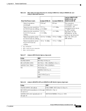
..., Class A IEC 60950 with Amendments A1 through A4 EN55022/CISPR22, Class A, 1998 OL-6156-01 Catalyst 2950 Switch Hardware Installation Guide A-5 Appendix A Technical Specifications Table A-6 Fiber-Optic Port Specifications for Catalyst 2950C-24, Catalyst 2950SX-24, and Catalyst 2950 LRE Switches Fiber-Port Power Levels Catalyst 2950C-24 Optical transmitter wavelength 1300 nm1 Optical receiver sensitivity -33.5 to for 50/125-micron cabling -11...
..., Class A IEC 60950 with Amendments A1 through A4 EN55022/CISPR22, Class A, 1998 OL-6156-01 Catalyst 2950 Switch Hardware Installation Guide A-5 Appendix A Technical Specifications Table A-6 Fiber-Optic Port Specifications for Catalyst 2950C-24, Catalyst 2950SX-24, and Catalyst 2950 LRE Switches Fiber-Port Power Levels Catalyst 2950C-24 Optical transmitter wavelength 1300 nm1 Optical receiver sensitivity -33.5 to for 50/125-micron cabling -11...

Hardware Installation Guide
Page 96
Appendix A Technical Specifications Table A-8 Catalyst 2950ST-8 LRE and 2950ST-24 LRE Switch Agency Approvals (continued) Safety EMC TUV-GS to EN60950 with Amendments EN 55024: ITE Immunity Standard. (CE Mark), 1998 A1 through A4 and A11 CE .../IEC1000-4-11: Immunity to Voltage Dips, Voltage Variations, and Short Voltage Interruptions AS/NZS 3548, Class A BSMI, Class A VCCI, Class A MIC Mark Table A-9 Catalyst 2950ST-24 LRE 997 Switch Agency Approvals Safety EMC UL/CSA 60950, 3rd edition USA CFR47, FCC, Part 15, Class A IEC 60950 with Amendments A1 through ICES-003, Class...
Appendix A Technical Specifications Table A-8 Catalyst 2950ST-8 LRE and 2950ST-24 LRE Switch Agency Approvals (continued) Safety EMC TUV-GS to EN60950 with Amendments EN 55024: ITE Immunity Standard. (CE Mark), 1998 A1 through A4 and A11 CE .../IEC1000-4-11: Immunity to Voltage Dips, Voltage Variations, and Short Voltage Interruptions AS/NZS 3548, Class A BSMI, Class A VCCI, Class A MIC Mark Table A-9 Catalyst 2950ST-24 LRE 997 Switch Agency Approvals Safety EMC UL/CSA 60950, 3rd edition USA CFR47, FCC, Part 15, Class A IEC 60950 with Amendments A1 through ICES-003, Class...