
Hardware Installation Guide
Page 5
... Documentation xvii Documentation Feedback xviii Obtaining Technical Assistance xviii Cisco.com xviii Technical Assistance Center xix Contacting TAC by Using the Cisco TAC Website xix Contacting TAC by Telephone xx Product Overview 1-1 Features 1-1 Management Interface Options 1-4 Front-Panel Description 1-4 10/100 Ports 1-6 100BASE-FX Ports 1-7 Long-Reach Ethernet Ports 1-7 Catalyst 2900 Series XL Hardware Installation Guide v
... Documentation xvii Documentation Feedback xviii Obtaining Technical Assistance xviii Cisco.com xviii Technical Assistance Center xix Contacting TAC by Using the Cisco TAC Website xix Contacting TAC by Telephone xx Product Overview 1-1 Features 1-1 Management Interface Options 1-4 Front-Panel Description 1-4 10/100 Ports 1-6 100BASE-FX Ports 1-7 Long-Reach Ethernet Ports 1-7 Catalyst 2900 Series XL Hardware Installation Guide v

Hardware Installation Guide
Page 6
... 1-21 DC Power Connector 1-21 Cisco RPS Connector 1-22 Console Port 1-23 2 C H A P T E R Installation 2-1 Preparing for Installation 2-1 Warnings 2-1 EMC Regulatory Statements 2-4 U.S.A. 2-4 Taiwan 2-4 Japan 2-5 Korea 2-5 Hungary 2-6 Installation Guidelines 2-6 Verifying Package Contents 2-7 Installing the Switch on a Table or Shelf 2-9 Installing the Switch in a Rack 2-9 Removing Screws from the Switch 2-11 Attaching the Brackets to a Catalyst 2912 XL, 2924C XL...
... 1-21 DC Power Connector 1-21 Cisco RPS Connector 1-22 Console Port 1-23 2 C H A P T E R Installation 2-1 Preparing for Installation 2-1 Warnings 2-1 EMC Regulatory Statements 2-4 U.S.A. 2-4 Taiwan 2-4 Japan 2-5 Korea 2-5 Hungary 2-6 Installation Guidelines 2-6 Verifying Package Contents 2-7 Installing the Switch on a Table or Shelf 2-9 Installing the Switch in a Rack 2-9 Removing Screws from the Switch 2-11 Attaching the Brackets to a Catalyst 2912 XL, 2924C XL...

Hardware Installation Guide
Page 7
...the Switch 2-26 Wiring the DC-Input Power Source 2-29 Connecting to a 10/100 Port 2-35 Connecting to a 100BASE-FX Port 2-37 Connecting to an LRE Port 2-38 Connecting to a Module Port 2-42 Connecting to the Console Port 2-...42 Where to Go Next 2-43 Troubleshooting 3-1 Understanding POST Results 3-1 Correcting Module POST Failures 3-2 Diagnosing Problems 3-3 Technical Specifications A-1 Connectors and Cable Specifications B-1 Connector Specifications B-1 10/100 Ports B-1 100BASE-FX Ports B-2 Contents 78-6461-04 Catalyst...
...the Switch 2-26 Wiring the DC-Input Power Source 2-29 Connecting to a 10/100 Port 2-35 Connecting to a 100BASE-FX Port 2-37 Connecting to an LRE Port 2-38 Connecting to a Module Port 2-42 Connecting to the Console Port 2-...42 Where to Go Next 2-43 Troubleshooting 3-1 Understanding POST Results 3-1 Correcting Module POST Failures 3-2 Diagnosing Problems 3-3 Technical Specifications A-1 Connectors and Cable Specifications B-1 Connector Specifications B-1 10/100 Ports B-1 100BASE-FX Ports B-2 Contents 78-6461-04 Catalyst...

Hardware Installation Guide
Page 8
...Straight-Through Cable Pinouts B-4 RJ-21 Cable Pinouts B-5 Console Port B-5 Identifying a Rollover Cable B-6 Connecting to a PC B-6 Connecting to a Terminal B-7 Translated Safety Warnings C-1 Attaching the Cisco RPS (model PWR600-AC-RPS) C-1 Attaching the Cisco RPS (model PWR300-AC-RPS-N1) C-2 Qualified Personnel ... Warning C-11 Circuit Breaker (15A) Warning C-12 Grounded Equipment Warning C-14 Supply Circuit Warning C-15 Voltage Warning C-16 Power Supply Warning C-17 Lightning Activity Warning C-19 Product Disposal Warning C-21 Catalyst 2900 Series XL Hardware Installation Guide viii 78-...
...Straight-Through Cable Pinouts B-4 RJ-21 Cable Pinouts B-5 Console Port B-5 Identifying a Rollover Cable B-6 Connecting to a PC B-6 Connecting to a Terminal B-7 Translated Safety Warnings C-1 Attaching the Cisco RPS (model PWR600-AC-RPS) C-1 Attaching the Cisco RPS (model PWR300-AC-RPS-N1) C-2 Qualified Personnel ... Warning C-11 Circuit Breaker (15A) Warning C-12 Grounded Equipment Warning C-14 Supply Circuit Warning C-15 Voltage Warning C-16 Power Supply Warning C-17 Lightning Activity Warning C-19 Product Disposal Warning C-21 Catalyst 2900 Series XL Hardware Installation Guide viii 78-...

Hardware Installation Guide
Page 11
...-6461-04 Catalyst 2900 Series XL Hardware Installation Guide xi Organization This guide is for the networking or computer technician responsible for installing a switch in a rack, on a desk, or on a wall. Preface Audience This guide is organized into the following chapters: Chapter 1, "Product Overview," summarizes the switch features and describes the ports, the standards...
...-6461-04 Catalyst 2900 Series XL Hardware Installation Guide xi Organization This guide is for the networking or computer technician responsible for installing a switch in a rack, on a desk, or on a wall. Preface Audience This guide is organized into the following chapters: Chapter 1, "Product Overview," summarizes the switch features and describes the ports, the standards...

Hardware Installation Guide
Page 21
...port 78-6461-04 Catalyst 2900 Series XL Hardware Installation Guide 1-1 The 2900 XL LRE switches employ Long-Reach Ethernet (LRE), a very-high-data-rate digital subscriber line (VDSL)-based technology that describe the Catalyst 2900 series XL switches, hereafter referred to as the switches. • Switch... the LEDs Features The switches are stackable 10/100 Ethernet switches to which you can be deployed as servers, routers, and other network devices. The switches can connect workstations, Cisco IP Phones, and other network devices such as backbone switches, aggregating 10/100 and...
...port 78-6461-04 Catalyst 2900 Series XL Hardware Installation Guide 1-1 The 2900 XL LRE switches employ Long-Reach Ethernet (LRE), a very-high-data-rate digital subscriber line (VDSL)-based technology that describe the Catalyst 2900 series XL switches, hereafter referred to as the switches. • Switch... the LEDs Features The switches are stackable 10/100 Ethernet switches to which you can be deployed as servers, routers, and other network devices. The switches can connect workstations, Cisco IP Phones, and other network devices such as backbone switches, aggregating 10/100 and...

Hardware Installation Guide
Page 22
... asynchronous transfer mode (ATM) modules • On the Catalyst 2924M XL DC switch, a direct current (DC) power converter • On the Catalyst 2912 LRE XL and 2924 LRE XL switches, up to 24 LRE ports through one RJ-21 connector and hot swapping capability with the Cisco LRE customer premises equipment (CPE) devices • Supports up...
... asynchronous transfer mode (ATM) modules • On the Catalyst 2924M XL DC switch, a direct current (DC) power converter • On the Catalyst 2912 LRE XL and 2924 LRE XL switches, up to 24 LRE ports through one RJ-21 connector and hot swapping capability with the Cisco LRE customer premises equipment (CPE) devices • Supports up...

Hardware Installation Guide
Page 23
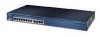
Chapter 1 Product Overview Figure 1-1 Catalyst 2900 Series XL Switches Version Number Description WS-C2912-LRE-XL 4 fixed autosensing 10/100 ports INPUT OUTPUT PWR PWR RESET TEMP FAN 9X 10X 11X 12X 12 LRE ports Cisco RPS 300 WS-C2924-LRE-XL 4 fixed autosensing 10/100 ports 24 LRE ports INPUT OUTPUT PWR PWR RESET TEMP FAN 9X 10X...
Chapter 1 Product Overview Figure 1-1 Catalyst 2900 Series XL Switches Version Number Description WS-C2912-LRE-XL 4 fixed autosensing 10/100 ports INPUT OUTPUT PWR PWR RESET TEMP FAN 9X 10X 11X 12X 12 LRE ports Cisco RPS 300 WS-C2924-LRE-XL 4 fixed autosensing 10/100 ports 24 LRE ports INPUT OUTPUT PWR PWR RESET TEMP FAN 9X 10X...

Hardware Installation Guide
Page 24
...Reach Ethernet ports (See Figure 1-4). The switch supports a comprehensive set of MIB extensions and four Remote Monitoring (RMON) groups. You can also display network topologies to gather link information and to display switch images to the Catalyst 2900 Series XL and Catalyst 3500 Series ...XL Software Configuration Guide. Front-Panel Description Depending on the switch. Catalyst 2900 Series XL Hardware Installation Guide 1-4 78-6461-04 Using...
...Reach Ethernet ports (See Figure 1-4). The switch supports a comprehensive set of MIB extensions and four Remote Monitoring (RMON) groups. You can also display network topologies to gather link information and to display switch images to the Catalyst 2900 Series XL and Catalyst 3500 Series ...XL Software Configuration Guide. Front-Panel Description Depending on the switch. Catalyst 2900 Series XL Hardware Installation Guide 1-4 78-6461-04 Using...
Hardware Installation Guide
Page 25
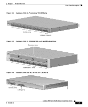
... 20X 21X 22X Catalyst10209B0AS0ES-FEXRIES XL 23 24 10/100 ports 100BASE-FX ports Figure 1-3 Catalyst 2900 XL 100BASE-FX ports and Module Slots Expansion slots 47286 12 1 MODE 2 3 Catalyst 2900 SERIES XL 4 5 100BASE-FX 6 7 8 9 10 11 12 100BASE-FX ports Figure 1-4 Catalyst 2900 LRE XL 10/100 and LRE Ports INPUT OUTPUT PWR PWR RESET TEMP FAN 9X 10X...
... 20X 21X 22X Catalyst10209B0AS0ES-FEXRIES XL 23 24 10/100 ports 100BASE-FX ports Figure 1-3 Catalyst 2900 XL 100BASE-FX ports and Module Slots Expansion slots 47286 12 1 MODE 2 3 Catalyst 2900 SERIES XL 4 5 100BASE-FX 6 7 8 9 10 11 12 100BASE-FX ports Figure 1-4 Catalyst 2900 LRE XL 10/100 and LRE Ports INPUT OUTPUT PWR PWR RESET TEMP FAN 9X 10X...

Hardware Installation Guide
Page 26
... 100BASE-TX traffic. When set for more info on the Catalyst 2900 XL switches provide protocol support for autonegotiation, the port senses the speed and duplex settings of half duplex, full duplex, 10 Mbps, or 100 Mbps. Cisco IP Phones-connected to the 10/100 port-must be connected to 328 feet (100 meters) away...
... 100BASE-TX traffic. When set for more info on the Catalyst 2900 XL switches provide protocol support for autonegotiation, the port senses the speed and duplex settings of half duplex, full duplex, 10 Mbps, or 100 Mbps. Cisco IP Phones-connected to the 10/100 port-must be connected to 328 feet (100 meters) away...

Hardware Installation Guide
Page 27
... other telephone services are configured for each CPE device can hot swap the CPE devices without powering down the switch or disrupting the other switch ports. For information about the Cisco LRE CPE devices, refer to the Catalyst 2900 Series XL and Catalyst 3500 Series XL Software Configuration Guide. For more information about configuring the LRE...
... other telephone services are configured for each CPE device can hot swap the CPE devices without powering down the switch or disrupting the other switch ports. For information about the Cisco LRE CPE devices, refer to the Catalyst 2900 Series XL and Catalyst 3500 Series XL Software Configuration Guide. For more information about configuring the LRE...

Hardware Installation Guide
Page 28
...branch exchange (PBX) switch telephones that the module slots support. For more information about homologated POTS splitters, contact your Cisco sales representative. Each module port is managed through the switch management interfaces. Front-...Panel Description Chapter 1 Product Overview (PSTN). For more information about the Cisco LRE 48 POTS Splitter (PS-1M-LRE-48), refer to other switch ports and is internally switched to the Installation Notes for the Catalyst...
...branch exchange (PBX) switch telephones that the module slots support. For more information about homologated POTS splitters, contact your Cisco sales representative. Each module port is managed through the switch management interfaces. Front-...Panel Description Chapter 1 Product Overview (PSTN). For more information about the Cisco LRE 48 POTS Splitter (PS-1M-LRE-48), refer to other switch ports and is internally switched to the Installation Notes for the Catalyst...

Hardware Installation Guide
Page 29
... Guide 1-9 Note Modules WS-X2914-XL and WS-X2922-XL support 2048 MAC addresses. Changing a port mode changes the information provided by restarting that you use the switch LEDs to the Release Notes for Catalyst 2900 series XL switches. Chapter 1 Product Overview Front-Panel Description Table 1-1 Expansion Modules (continued) Module Type Model Number 1000BASE...
... Guide 1-9 Note Modules WS-X2914-XL and WS-X2922-XL support 2048 MAC addresses. Changing a port mode changes the information provided by restarting that you use the switch LEDs to the Release Notes for Catalyst 2900 series XL switches. Chapter 1 Product Overview Front-Panel Description Table 1-1 Expansion Modules (continued) Module Type Model Number 1000BASE...

Hardware Installation Guide
Page 30
...Port mode LEDs MODE 1X 2X 3X 4X 5X 6X 7X Mode RPS button LED 47288 1-10 Catalyst 2900 Series XL Hardware Installation Guide 78-6461-04 The Catalyst 2900 Series XL and Catalyst 3500 Series XL Software Configuration Guide describes how to use CMS to manage standalone or individual switches... and how to use cluster management software to manage switch clusters]. Front-Panel Description Chapter 1 ...
...Port mode LEDs MODE 1X 2X 3X 4X 5X 6X 7X Mode RPS button LED 47288 1-10 Catalyst 2900 Series XL Hardware Installation Guide 78-6461-04 The Catalyst 2900 Series XL and Catalyst 3500 Series XL Software Configuration Guide describes how to use CMS to manage standalone or individual switches... and how to use cluster management software to manage switch clusters]. Front-Panel Description Chapter 1 ...

Hardware Installation Guide
Page 31
Chapter 1 Product Overview Figure 1-6 Catalyst 2912MF XL, 2924M XL, and 2924M XL DC LEDs 10BASE-FX port LEDs Front-Panel Description 12 1 MODE 2 3 4 5 100BASE-FX 6 7 System LED RPS LED Expansion slot status LED Port mode LED Mode button 48003 78-6461-04 Catalyst 2900 Series XL Hardware Installation Guide 1-11
Chapter 1 Product Overview Figure 1-6 Catalyst 2912MF XL, 2924M XL, and 2924M XL DC LEDs 10BASE-FX port LEDs Front-Panel Description 12 1 MODE 2 3 4 5 100BASE-FX 6 7 System LED RPS LED Expansion slot status LED Port mode LED Mode button 48003 78-6461-04 Catalyst 2900 Series XL Hardware Installation Guide 1-11

Hardware Installation Guide
Page 32
System is receiving power but is receiving power and functioning properly. Front-Panel Description Figure 1-7 Catalyst 2912 LRE XL and 2924 LRE XL LEDs 10/100 port LEDs Chapter 1 Product Overview SYSTEM RPS MODE LRE STAT DUPLX SPEED Mode button 1X 2X 3X 4X System LED RPS LED LRE ... LRE port LEDs 1-12 LRE port LEDs 13-24 48002 System LED The system LED shows whether the system is not functioning properly. System is not powered up. For information on the System LED colors during POST, see the "Powering On the Switch and Running POST" section on page 2-24. 1-12 Catalyst 2900 ...
System is receiving power but is receiving power and functioning properly. Front-Panel Description Figure 1-7 Catalyst 2912 LRE XL and 2924 LRE XL LEDs 10/100 port LEDs Chapter 1 Product Overview SYSTEM RPS MODE LRE STAT DUPLX SPEED Mode button 1X 2X 3X 4X System LED RPS LED LRE ... LRE port LEDs 1-12 LRE port LEDs 13-24 48002 System LED The system LED shows whether the system is not functioning properly. System is not powered up. For information on the System LED colors during POST, see the "Powering On the Switch and Running POST" section on page 2-24. 1-12 Catalyst 2900 ...

Hardware Installation Guide
Page 34
... Port Mode Port status Switch utilization Port duplex mode Port speed Description The port status. Contact Cisco Systems. The internal power supply in use by the switch. (See Figure 1-8.) The port duplex mode: full duplex or half duplex, and default modes: • 10/100 ports: auto • 100BaseFX ports: auto • Gigabit ports: auto The port operating speed: 10 or 100 Mbps. 1-14 Catalyst...
... Port Mode Port status Switch utilization Port duplex mode Port speed Description The port status. Contact Cisco Systems. The internal power supply in use by the switch. (See Figure 1-8.) The port duplex mode: full duplex or half duplex, and default modes: • 10/100 ports: auto • 100BaseFX ports: auto • Gigabit ports: auto The port operating speed: 10 or 100 Mbps. 1-14 Catalyst...

Hardware Installation Guide
Page 35
Chapter 1 Product Overview Front-Panel Description Table 1-5 Port Mode LEDs on Catalyst 2912 LRE XL and 2924 LRE XL Switches Mode LED LRE STAT DUPLX SPEED Port Mode LRE link status Port status Port duplex mode Port speed Description Long-Reach Ethernet (LRE) link status of the 10/100 or 100BASE-FX switch ports or the Ethernet link status on...
Chapter 1 Product Overview Front-Panel Description Table 1-5 Port Mode LEDs on Catalyst 2912 LRE XL and 2924 LRE XL Switches Mode LED LRE STAT DUPLX SPEED Port Mode LRE link status Port status Port duplex mode Port speed Description Long-Reach Ethernet (LRE) link status of the 10/100 or 100BASE-FX switch ports or the Ethernet link status on...
Hardware Installation Guide
Page 36
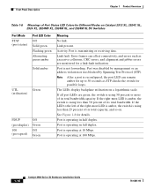
... 30 seconds as excessive collisions, CRC errors, and alignment and jabber errors are green, the switch is operating at 100 Mbps. 1-16 Catalyst 2900 Series XL Hardware Installation Guide 78-6461-04 Port is using less than 25 percent of its total capacity, and so on a logarithmic scale....most LED is amber, the switch is reconfigured, the port LED can affect connectivity, and errors such as STP checks the switch for Different Modes on Catalyst 2912 XL, 2924C XL, 2924 XL, 2924MF XL, 2924M XL, and 2924M XL DC Switches Port Mode STAT (port status) Port LED Color Off Solid green ...
... 30 seconds as excessive collisions, CRC errors, and alignment and jabber errors are green, the switch is operating at 100 Mbps. 1-16 Catalyst 2900 Series XL Hardware Installation Guide 78-6461-04 Port is using less than 25 percent of its total capacity, and so on a logarithmic scale....most LED is amber, the switch is reconfigured, the port LED can affect connectivity, and errors such as STP checks the switch for Different Modes on Catalyst 2912 XL, 2924C XL, 2924 XL, 2924MF XL, 2924M XL, and 2924M XL DC Switches Port Mode STAT (port status) Port LED Color Off Solid green ...


