
Remote Camera Controller User Manual Basic
Page 3
... to cause harmful interference in the air will be connected to recovery or replacement of Conformity Model Number: RC-IP100 Trade Name: Canon Responsible Party: Canon U.S.A., Inc. Note: This equipment has been tested and found to comply with the user manual, may ...or a shelf, make any reason whatsoever. Declaration of lost content. Telephone Number: 1-800-OK-CANON (1-800-652-2666) FCC NOTICE Remote Camera Controller, Model Name: RC-IP100 This device complies with the valid European directives and standards regarding electromagnetic compatibility and electrical safety. Do...
... to cause harmful interference in the air will be connected to recovery or replacement of Conformity Model Number: RC-IP100 Trade Name: Canon Responsible Party: Canon U.S.A., Inc. Note: This equipment has been tested and found to comply with the user manual, may ...or a shelf, make any reason whatsoever. Declaration of lost content. Telephone Number: 1-800-OK-CANON (1-800-652-2666) FCC NOTICE Remote Camera Controller, Model Name: RC-IP100 This device complies with the valid European directives and standards regarding electromagnetic compatibility and electrical safety. Do...

Remote Camera Controller User Manual Basic
Page 4
... this type of waste could result in fuse. For more information regarding return and recycling of WEEE products, please visit www.canon-europe.com/sustainability/approach/. 4 Safety Precautions If you are not sure of the type of power supply of your home, consult...to a designated collection point, e.g., on equipment. The power cord attached conforms to rain or moisture. European Union regulatory notices: Remote Camera Controller, Model Name: RC-IP100 Warning This is AC 220 - 240 V (For European countries, Asian countries, and United Kingdom). This product should be sure to ...
... this type of waste could result in fuse. For more information regarding return and recycling of WEEE products, please visit www.canon-europe.com/sustainability/approach/. 4 Safety Precautions If you are not sure of the type of power supply of your home, consult...to a designated collection point, e.g., on equipment. The power cord attached conforms to rain or moisture. European Union regulatory notices: Remote Camera Controller, Model Name: RC-IP100 Warning This is AC 220 - 240 V (For European countries, Asian countries, and United Kingdom). This product should be sure to ...

Remote Camera Controller User Manual Basic
Page 20
Memo : Describes reference information, such as functions and usage restrictions of this product, do not lift this unit while holding the control lever. Contents of the manual may melt or tarnish its surface. We have any maintenance. do so appropriately by wiping with a dry cloth. For tough ...
Memo : Describes reference information, such as functions and usage restrictions of this product, do not lift this unit while holding the control lever. Contents of the manual may melt or tarnish its surface. We have any maintenance. do so appropriately by wiping with a dry cloth. For tough ...

Remote Camera Controller User Manual Basic
Page 21
E Zoom lever For performing the zoom operation of the remote camera. G POWER lamp Green : Lights up when the alarm is turned on the website. H Control lever For operating pan/tilt of the remote camera. B Wire Clamp For preventing the AC adapter cable from falling out. H SERIAL terminal For connecting a serial ...
E Zoom lever For performing the zoom operation of the remote camera. G POWER lamp Green : Lights up when the alarm is turned on the website. H Control lever For operating pan/tilt of the remote camera. B Wire Clamp For preventing the AC adapter cable from falling out. H SERIAL terminal For connecting a serial ...

Remote Camera Controller User Manual Basic
Page 22
...screen does not appear, select [HOME] to display the home screen. Connection Diagram Serial camera IP camera IP camera HUB LAN cable RS-422 cable RC-IP100 . * Up to 100 cameras can be operated, perform the above procedures again. A Select [SETTINGS] on the unit. A Select [SETTINGS] on...green. 2 Configure the settings of this unit. 0 Set the IP address of this unit to "On". C Select [CAMERA REGISTRATION]. C Select [CONTROLLER]. 0 The IP address setting screen appears. Action Turn off the power switch at the rear of this unit as follows. D Perform registration according ...
...screen does not appear, select [HOME] to display the home screen. Connection Diagram Serial camera IP camera IP camera HUB LAN cable RS-422 cable RC-IP100 . * Up to 100 cameras can be operated, perform the above procedures again. A Select [SETTINGS] on the unit. A Select [SETTINGS] on...green. 2 Configure the settings of this unit. 0 Set the IP address of this unit to "On". C Select [CAMERA REGISTRATION]. C Select [CONTROLLER]. 0 The IP address setting screen appears. Action Turn off the power switch at the rear of this unit as follows. D Perform registration according ...

Remote Camera Controller User Manual Basic
Page 23
... V Current consumption 0.6 A Mass Approx. 2.1 kg Surrounding temperature 0 °C to 40 °C (32 °F to 104 °F) (operation) Allowable operating 20 %RH to the Remote Camera Controller RC-IP100"on the product (firmware, User Manual, etc.), please visit our website. Please note that some features might not be usable depending on the camera in...
... V Current consumption 0.6 A Mass Approx. 2.1 kg Surrounding temperature 0 °C to 40 °C (32 °F to 104 °F) (operation) Allowable operating 20 %RH to the Remote Camera Controller RC-IP100"on the product (firmware, User Manual, etc.), please visit our website. Please note that some features might not be usable depending on the camera in...

Remote Camera Controller User Manual
Page 1
ENGLISH Remote Camera Controller User Manual Make sure to read through this document may differ. Regarding the functions changed/added by the latest firmware, the actual operation and the contents on this User Manual before using the product. Please check the "Updated Information" in this document for new functions and specification changes.
ENGLISH Remote Camera Controller User Manual Make sure to read through this document may differ. Regarding the functions changed/added by the latest firmware, the actual operation and the contents on this User Manual before using the product. Please check the "Updated Information" in this document for new functions and specification changes.

Remote Camera Controller User Manual
Page 3
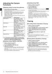
... 8 Changing an Assigned Function 9 Selecting a Preset 9 Adjusting the Camera Functions 10 Adjusting Using Function Group Buttons 10 Adjusting Using CAMERA CONTROL 10 Adjusting Using FUNC 10 Tracing 10 Recording Camera Operations (Tracing 10 Playing Camera Operations (Tracing 10 Settings Setup Flow 11 Basic Operations ...Off 15 Camera Settings Menu 15 Network Settings 16 Camera Network Settings 16 Network Settings on This Controller 16 Tally Setup 17 Tally Control Interface 17 Others Troubleshooting 18 Third-party Software 18 Connection Diagram 18 Specifications 19 Make sure ...
... 8 Changing an Assigned Function 9 Selecting a Preset 9 Adjusting the Camera Functions 10 Adjusting Using Function Group Buttons 10 Adjusting Using CAMERA CONTROL 10 Adjusting Using FUNC 10 Tracing 10 Recording Camera Operations (Tracing 10 Playing Camera Operations (Tracing 10 Settings Setup Flow 11 Basic Operations ...Off 15 Camera Settings Menu 15 Network Settings 16 Camera Network Settings 16 Network Settings on This Controller 16 Tally Setup 17 Tally Control Interface 17 Others Troubleshooting 18 Third-party Software 18 Connection Diagram 18 Specifications 19 Make sure ...

Remote Camera Controller User Manual
Page 4
...dry cloth. Also enables smooth pan/tilt operation. Do not apply excessive force to a maximum of the respective companies. Wiping with this unit; Controls up to this product only. The bundled AC adapter and power cord are to vibrations. Wipe using it does not fall from the desktop ... Do not leave this unit is exclusively designed for long hours. For tough stains, wipe using or placing this unit while holding the control lever. They cannot be used with thinner or benzene may melt or tarnish its versatile screen configuration. Handling Precautions Do not rub against...
...dry cloth. Also enables smooth pan/tilt operation. Do not apply excessive force to a maximum of the respective companies. Wiping with this unit; Controls up to this product only. The bundled AC adapter and power cord are to vibrations. Wipe using it does not fall from the desktop ... Do not leave this unit is exclusively designed for long hours. For tough stains, wipe using or placing this unit while holding the control lever. They cannot be used with thinner or benzene may melt or tarnish its versatile screen configuration. Handling Precautions Do not rub against...

Remote Camera Controller User Manual
Page 5
... 12V terminal For connecting the supplied AC adapter. H SERIAL terminal For connecting a serial cable. E Zoom lever For performing the zoom operation of the remote camera. H Control lever For operating pan/tilt of the remote camera. Memo : 0 The specifications of the terminals are as a touch panel. Getting Started Name of Parts Front...
... 12V terminal For connecting the supplied AC adapter. H SERIAL terminal For connecting a serial cable. E Zoom lever For performing the zoom operation of the remote camera. H Control lever For operating pan/tilt of the remote camera. Memo : 0 The specifications of the terminals are as a touch panel. Getting Started Name of Parts Front...

Remote Camera Controller User Manual
Page 7
... according to the camera to be operated, perform the above procedures again. S [STORE] Tap the button to enter [DELETE] mode. C Select [CONTROLLER]. 0 The IP address setting screen appears. U [CAMERA/PRESET] For selecting a camera number or preset number. D Enter the IP address and tap... : 0 For details on and off disables the pan/tilt operation by the control lever. T [VIEW] Tap the button to replicate the operations at the same time. Getting Started N [CAMERA CONTROL] For controlling the currently selected camera. P [TRACE] For recording the camera operations of the...
... according to the camera to be operated, perform the above procedures again. S [STORE] Tap the button to enter [DELETE] mode. C Select [CONTROLLER]. 0 The IP address setting screen appears. U [CAMERA/PRESET] For selecting a camera number or preset number. D Enter the IP address and tap... : 0 For details on and off disables the pan/tilt operation by the control lever. T [VIEW] Tap the button to replicate the operations at the same time. Getting Started N [CAMERA CONTROL] For controlling the currently selected camera. P [TRACE] For recording the camera operations of the...

Remote Camera Controller User Manual
Page 8
... "Changing an Assigned Function") 2 Turn the F1 knob. Operating a Camera Operating the PTZ (pan/ tilt/ zoom) 1 Select a camera to operate. (A P8 "Selecting a Camera") 2 Tilt the control lever toward the direction you want the camera to move (pan/ tilt operation). 0 Tilt the lever to the left /right buttons of [CAM Number] at...
... "Changing an Assigned Function") 2 Turn the F1 knob. Operating a Camera Operating the PTZ (pan/ tilt/ zoom) 1 Select a camera to operate. (A P8 "Selecting a Camera") 2 Tilt the control lever toward the direction you want the camera to move (pan/ tilt operation). 0 Tilt the lever to the left /right buttons of [CAM Number] at...
Remote Camera Controller User Manual
Page 10
...followed by tapping the [White Balance] button, the [USER1] button can be adjustable depending on the camera that is connected. Adjusting Using CAMERA CONTROL 1 Select a camera to execute tracing. The adjustable items are as follows. Memo : 0 Tapping the [Cancel] button stops the tracing ... to shift to the position to start tracing. 5 Tap the [Execute Trace] button to operate. (A P8 "Selecting a Camera") 2 Tap the [CAMERA CONTROL] tab. 3 Adjust the Functions. The adjustable items are as follows. Note that is connected. [White Balance], [Gain], [Shutter], [Iris] (AUTO ON...
...followed by tapping the [White Balance] button, the [USER1] button can be adjustable depending on the camera that is connected. Adjusting Using CAMERA CONTROL 1 Select a camera to execute tracing. The adjustable items are as follows. Memo : 0 Tapping the [Cancel] button stops the tracing ... to shift to the position to start tracing. 5 Tap the [Execute Trace] button to operate. (A P8 "Selecting a Camera") 2 Tap the [CAMERA CONTROL] tab. 3 Adjust the Functions. The adjustable items are as follows. Note that is connected. [White Balance], [Gain], [Shutter], [Iris] (AUTO ON...

Remote Camera Controller User Manual
Page 11
...buttons and knobs of this unit. (A P9 "Changing an Assigned Function") Basic Operations of Menu Screen 1 Tap the [SETTINGS] button on This Controller") o Touch Screen Allows you to calibrate the operation panel. Tapping the button changes the button color. Tapping the button changes the button color....the settings for the first time, or when new cameras are added, set up the connected camera. (A P15 "Camera Settings Menu") 3 Remote control settings For configuring the functions to a button. Tapping the [ENTER] button in the manner as follows. Settings Menu o Video Allows you to switch...
...buttons and knobs of this unit. (A P9 "Changing an Assigned Function") Basic Operations of Menu Screen 1 Tap the [SETTINGS] button on This Controller") o Touch Screen Allows you to calibrate the operation panel. Tapping the button changes the button color. Tapping the button changes the button color....the settings for the first time, or when new cameras are added, set up the connected camera. (A P15 "Camera Settings Menu") 3 Remote control settings For configuring the functions to a button. Tapping the [ENTER] button in the manner as follows. Settings Menu o Video Allows you to switch...

Remote Camera Controller User Manual
Page 12
VIEW Screen CAMERA/PRESET Screen CAMERA CONTROL Screen TRACE Screen FUNC Screen STORE Screen This screen is used for selecting a camera, selecting a camera preset, operating a camera and performing tracing. The flow of normal menu screen and settings menu screen. Home Screen . STORE Screen CAMERA/PRESET Screen TRACE Screen 12 Menu Screen Flow Settings Menu Screen Flow o The menu screens consist of the each screen is as shown in the figures below. Home Screen . Normal Menu Screen VIEW Screen This screen is used for registering a camera preset or tracing.
VIEW Screen CAMERA/PRESET Screen CAMERA CONTROL Screen TRACE Screen FUNC Screen STORE Screen This screen is used for selecting a camera, selecting a camera preset, operating a camera and performing tracing. The flow of normal menu screen and settings menu screen. Home Screen . STORE Screen CAMERA/PRESET Screen TRACE Screen 12 Menu Screen Flow Settings Menu Screen Flow o The menu screens consist of the each screen is as shown in the figures below. Home Screen . Normal Menu Screen VIEW Screen This screen is used for registering a camera preset or tracing.

Remote Camera Controller User Manual
Page 14
Tap the [Back] button at the bottom left corner of the screen to return to the previous screen. Tap the [HOME] button at the top right corner of this unit. Video Screen ALL CAMERAS Screen SETTINGS Screen MENU Control Screen Function Screen CAMERA Group Screen Single Screen Network Screen CAMERA REGISTRATION Screen Touch Screen Screen CONTROLLER Screen 14 Menu Screen Flow Settings Settings Menu Screen SETTINGS Screen For configuring the settings of the screen to return to the home screen. (A P11 "Settings Menu") Home Screen .
Tap the [Back] button at the bottom left corner of the screen to return to the previous screen. Tap the [HOME] button at the top right corner of this unit. Video Screen ALL CAMERAS Screen SETTINGS Screen MENU Control Screen Function Screen CAMERA Group Screen Single Screen Network Screen CAMERA REGISTRATION Screen Touch Screen Screen CONTROLLER Screen 14 Menu Screen Flow Settings Settings Menu Screen SETTINGS Screen For configuring the settings of the screen to return to the home screen. (A P11 "Settings Menu") Home Screen .

Remote Camera Controller User Manual
Page 15
... used to confirm the setting. The digit of the number with non-existent camera within the same network, use the control lever and buttons to display the home screen. 2 Tap the [MENU Control] button on the screen. 2 Tap the [SETTINGS] button. Camera Settings Menu Making changes to the settings menu of...the camera to be configured. 0 Multiple cameras within the same group can be configured to "ON"/"OFF" only for cameras within the same network. 0 To control the Video output of a camera that do not correspond to any of the existing cameras are indicated in white. 6 Tap the [ON] or [OFF] ...
... used to confirm the setting. The digit of the number with non-existent camera within the same network, use the control lever and buttons to display the home screen. 2 Tap the [MENU Control] button on the screen. 2 Tap the [SETTINGS] button. Camera Settings Menu Making changes to the settings menu of...the camera to be configured. 0 Multiple cameras within the same group can be configured to "ON"/"OFF" only for cameras within the same network. 0 To control the Video output of a camera that do not correspond to any of the existing cameras are indicated in white. 6 Tap the [ON] or [OFF] ...

Remote Camera Controller User Manual
Page 16
.... 0 Numbers corresponding to this unit is registered with an IP camera. The SETTINGS screen appears. 3 Tap the [Network] button. 4 Tap the [CONTROLLER] button. o IP Camera [Manual] Tapping the [Manual] button displays the manual settings screen for IP address. 0 Tap the left/right buttons to select.... o IP Camera [AUTO] Tapping the [AUTO] button displays a message. If the home screen does not appear, tap the [HOME] button on This Controller . 1 Display the home screen. The SETTINGS screen appears. 3 Tap the [Network] button. 4 Tap the [CAMERA REGISTRATION] button. 5 Tap the button...
.... 0 Numbers corresponding to this unit is registered with an IP camera. The SETTINGS screen appears. 3 Tap the [Network] button. 4 Tap the [CONTROLLER] button. o IP Camera [Manual] Tapping the [Manual] button displays the manual settings screen for IP address. 0 Tap the left/right buttons to select.... o IP Camera [AUTO] Tapping the [AUTO] button displays a message. If the home screen does not appear, tap the [HOME] button on This Controller . 1 Display the home screen. The SETTINGS screen appears. 3 Tap the [Network] button. 4 Tap the [CAMERA REGISTRATION] button. 5 Tap the button...

Remote Camera Controller User Manual
Page 17
... 5 of the tally terminal should be changed. 1 5 6 9 12345678 ON . Voltage : Maximum DC 24 V Current : Maximum 50 mA RC-IP100 (Maximum voltage 24 V) TALLY OUT (Maximum current 50 mA) LED GND . Memo : 0 If a camera has been selected to receive tally ... OUTPUT-5 ON . 12345678 ON . 5 INPUT-5 12345678 OUTPUT-4 ON . 12345678 ON . 6 GND - 7 OUTPUT-1 - 8 OUTPUT-2 - 9 OUTPUT-3 - Settings Tally Setup Tally Control Interface Configure the pin 4 and pin 5 functions of the tally terminal using the SETTING switch on the tally input and tally output, refer to the...
... 5 of the tally terminal should be changed. 1 5 6 9 12345678 ON . Voltage : Maximum DC 24 V Current : Maximum 50 mA RC-IP100 (Maximum voltage 24 V) TALLY OUT (Maximum current 50 mA) LED GND . Memo : 0 If a camera has been selected to receive tally ... OUTPUT-5 ON . 12345678 ON . 5 INPUT-5 12345678 OUTPUT-4 ON . 12345678 ON . 6 GND - 7 OUTPUT-1 - 8 OUTPUT-2 - 9 OUTPUT-3 - Settings Tally Setup Tally Control Interface Configure the pin 4 and pin 5 functions of the tally terminal using the SETTING switch on the tally input and tally output, refer to the...

Remote Camera Controller User Manual
Page 19
... V Current consumption 0.6 A Mass Approx. 2.1 kg Surrounding temperature 0 °C to 40 °C (32 °F to 104 °F) (operation) Allowable operating 20 %RH to the Remote Camera Controller RC-IP100"on the product (firmware, User Manual, etc.), please visit our website.
... V Current consumption 0.6 A Mass Approx. 2.1 kg Surrounding temperature 0 °C to 40 °C (32 °F to 104 °F) (operation) Allowable operating 20 %RH to the Remote Camera Controller RC-IP100"on the product (firmware, User Manual, etc.), please visit our website.


