
Service Manual
Page 3
... for troubleshooting problems in the copier. -Note: The contents of this manual may be issued as necessary to cover major changes. CANON PC720174017501770 REV.0 AUG. 1994 PRINTED IN JAPAN omput AU JAPON) CHAPTER 3 "OPERATIONS AND TIMING" explains how the copier's electrical and mechanical systems are related to each other for servicing the machine in this Service Manual contains a set of appendixes consisting of copies. The PC720...
... for troubleshooting problems in the copier. -Note: The contents of this manual may be issued as necessary to cover major changes. CANON PC720174017501770 REV.0 AUG. 1994 PRINTED IN JAPAN omput AU JAPON) CHAPTER 3 "OPERATIONS AND TIMING" explains how the copier's electrical and mechanical systems are related to each other for servicing the machine in this Service Manual contains a set of appendixes consisting of copies. The PC720...
Service Manual
Page 9
...-the user may be replaced with considerations for ease in maintenance work to make jam removal easy. Uses a SURF fixing assembly. • The use of a charging roller helps to 1/000 of sizes between 70% and 141% may be selected. 2. Cassette accommodating various types of paper and 2-way pick-up. • The universal cassette (about 250 sheets) accommodates paper of existing machines) 3. GENERAL DESCRIPTION - Designed with a color toner cartridge (red...
...-the user may be replaced with considerations for ease in maintenance work to make jam removal easy. Uses a SURF fixing assembly. • The use of a charging roller helps to 1/000 of sizes between 70% and 141% may be selected. 2. Cassette accommodating various types of paper and 2-way pick-up. • The universal cassette (about 250 sheets) accommodates paper of existing machines) 3. GENERAL DESCRIPTION - Designed with a color toner cartridge (red...
Service Manual
Page 19
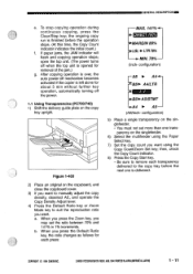
After copying operation is over, the auto power-off mechanism becomes activated if the copier is opened for removal of the jam.) g. MIN. 70% (Inch- configuration) r A5 ► A4-0- When you want using the Paper Select key. 7) Set the copy count you press the Default Ratio key, the ratio changes as follows for about 5 min without further key operation, automatically turning off when the top unit is...
After copying operation is over, the auto power-off mechanism becomes activated if the copier is opened for removal of the jam.) g. MIN. 70% (Inch- configuration) r A5 ► A4-0- When you want using the Paper Select key. 7) Set the copy count you press the Default Ratio key, the ratio changes as follows for about 5 min without further key operation, automatically turning off when the top unit is...
Service Manual
Page 22
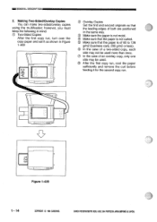
... the paper is not curled. ® Make sure that the paper is of 60 to 128 g/m2 (business card, 200 g/m2 or less). ® In the case of a two-sided copy, each side may be used . 0 After the first copy run, cool the paper sufficiently and remove the curl before feeding it for the second copy run , turn over the copy paper and set it...
... the paper is not curled. ® Make sure that the paper is of 60 to 128 g/m2 (business card, 200 g/m2 or less). ® In the case of a two-sided copy, each side may be used . 0 After the first copy run, cool the paper sufficiently and remove the curl before feeding it for the second copy run , turn over the copy paper and set it...
Service Manual
Page 24
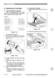
... open/close lever to have white lines or white spots; Replacing the Cartridge 1. A.1.•. :anon copier. Figure 1-414 2) Slide the old cartridge out of use the cartridge, a new cartridge should be obtained. see Figure 1-409. It ;e read this ME 'ith its tun 1. If the copy image has returned to normal, • Advise the user that, although he/she may continue to use . b. CANON...
... open/close lever to have white lines or white spots; Replacing the Cartridge 1. A.1.•. :anon copier. Figure 1-414 2) Slide the old cartridge out of use the cartridge, a new cartridge should be obtained. see Figure 1-409. It ;e read this ME 'ith its tun 1. If the copy image has returned to normal, • Advise the user that, although he/she may continue to use . b. CANON...
Service Manual
Page 25
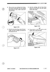
... RE© AUG.1994 PRINTEDIN JAPAN twat AUJAPON) 1 - 17 Figure 1-417 Figure 1-419 COPYRIGHT © 1994 CANON INC. GENERAL DESCRIPTION 3) Take out the new cartridge from its bag, and hold it horizontally with the Open label facing up, and insert it into the copier slowly until it stops. 0 7// Figure 1-416 4) Peel the end of the...
... RE© AUG.1994 PRINTEDIN JAPAN twat AUJAPON) 1 - 17 Figure 1-417 Figure 1-419 COPYRIGHT © 1994 CANON INC. GENERAL DESCRIPTION 3) Take out the new cartridge from its bag, and hold it horizontally with the Open label facing up, and insert it into the copier slowly until it stops. 0 7// Figure 1-416 4) Peel the end of the...
Service Manual
Page 26
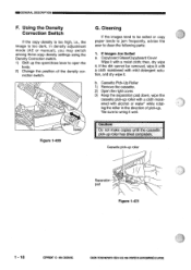
...* while rotating the roller in density adjustment mode (AE or manual), you may switch among three copy density settings using the Density Correction switch. 1) Shift up the open/close lever to open the body. 2) Change the position of pick-up. *Be sure to clean the following parts: 1. O G. CANON PC720/7408EORT0 REVS AUG. 1994 PRINTED IN JAPAN tIMPRIME AU JAPONI Using the Density Correction Switch If the copy density is too...
...* while rotating the roller in density adjustment mode (AE or manual), you may switch among three copy density settings using the Density Correction switch. 1) Shift up the open/close lever to open the body. 2) Change the position of pick-up. *Be sure to clean the following parts: 1. O G. CANON PC720/7408EORT0 REVS AUG. 1994 PRINTED IN JAPAN tIMPRIME AU JAPONI Using the Density Correction Switch If the copy density is too...
Service Manual
Page 42
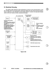
... motors, solenoids, and lamps. =OPERATIONS AND TIMING B. DC controller PCB Sensor • Scanner home position detection • Lens home position detection • Pre-registration roller paper detection • Delivery paper detection • Film displacement detection • Cartridge color detection • Cassette detection • Singlefeeder pick-up detection (PC720/740) Q101 CPU +5V +24V 4 Composite power supply PCB Q90O H Scanning lamp Fixing heater CPU Highvoltage...
... motors, solenoids, and lamps. =OPERATIONS AND TIMING B. DC controller PCB Sensor • Scanner home position detection • Lens home position detection • Pre-registration roller paper detection • Delivery paper detection • Film displacement detection • Cartridge color detection • Cassette detection • Singlefeeder pick-up detection (PC720/740) Q101 CPU +5V +24V 4 Composite power supply PCB Q90O H Scanning lamp Fixing heater CPU Highvoltage...
Service Manual
Page 45
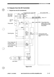
... from the DC Controller 1. J207-1 -2 AC driver J206-1 -2 J2O4-7 J104-1 HTRD Fixing heater drive signal; Scanning lamp FL1 Fluorescent lamp driver Microprocessor > Communication with composite power supply PCB Primary charging roller O Developing cylinder O Transfer charging roller O Static eliminator O Highvoltage circuit 00 Noise filter 00 PCB Door switch +5V +24V tt DC power supply circuit Figure 3-105 COPYRIGHT © 1994 CANON INC.
... from the DC Controller 1. J207-1 -2 AC driver J206-1 -2 J2O4-7 J104-1 HTRD Fixing heater drive signal; Scanning lamp FL1 Fluorescent lamp driver Microprocessor > Communication with composite power supply PCB Primary charging roller O Developing cylinder O Transfer charging roller O Static eliminator O Highvoltage circuit 00 Noise filter 00 PCB Door switch +5V +24V tt DC power supply circuit Figure 3-105 COPYRIGHT © 1994 CANON INC.
Service Manual
Page 50
... in continuous mode, (scanner reverse) in DIRECT. CANON PC72017407501770 REV.0 AUG.1994 PRINTED IN JAPAN (IMPRIME AU JAPON) generated, and the first sensitive drum and stabilizes sheet of copy paper is turned on the reproduction ratio. sensitive drum in preparation the pick-up signal is over and when the Copy Start key is picked up . SCRV While the scanner is moving The scanning lamp illuminates...
... in continuous mode, (scanner reverse) in DIRECT. CANON PC72017407501770 REV.0 AUG.1994 PRINTED IN JAPAN (IMPRIME AU JAPON) generated, and the first sensitive drum and stabilizes sheet of copy paper is turned on the reproduction ratio. sensitive drum in preparation the pick-up signal is over and when the Copy Start key is picked up . SCRV While the scanner is moving The scanning lamp illuminates...
Service Manual
Page 56
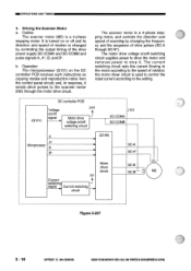
... driver circuit is turned on the DC controller PCB receives such instructions as copying modes and reproduction ratios from the control panel circuit; and, in response, it . Outline The scanner motor (M2) is a 4-phase stepping motor, and controls the direction and speed of scanning by controlling the output timing of rotation; b. Operation The microprocessor (Q101) on or off switching...
... driver circuit is turned on the DC controller PCB receives such instructions as copying modes and reproduction ratios from the control panel circuit; and, in response, it . Outline The scanner motor (M2) is a 4-phase stepping motor, and controls the direction and speed of scanning by controlling the output timing of rotation; b. Operation The microprocessor (Q101) on or off switching...
Service Manual
Page 68
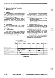
... the transfer roller can change the resistance of transfer bias application. CANON PC720/74000770 REV.O AUG.1994 PRINTED IN JAPAN pmpFeat AU JAPAN) see the descriptions for the function and output timing of toner to the photosensitive drum. • during last rotation. OPERATIONS AND TIMING F. Cleaning Bias The copier uses a direct charging method, and could allow adhesion of each time the Copy Start...
... the transfer roller can change the resistance of transfer bias application. CANON PC720/74000770 REV.O AUG.1994 PRINTED IN JAPAN pmpFeat AU JAPAN) see the descriptions for the function and output timing of toner to the photosensitive drum. • during last rotation. OPERATIONS AND TIMING F. Cleaning Bias The copier uses a direct charging method, and could allow adhesion of each time the Copy Start...

Service Manual
Page 70
...169; 1994 CANON CANON PC72011401150= RBA AUG.1994 PRINTED IN JAPAN (IMPRNE AU JAPONI The current detection circuit on the composite power supply PCB. During initial rotation after starting copying a. cific ...Copying The copier automatically corrects the application voltage during initial rotation after a press on signal to the transfer roller based on such data. The microprocessor on the composite power supply PCB. Controlling the Transfer Bias to a Specific Voltage The transfer bias is pressed, the copier feeds a specific current to a spe- =OPERATIONS AND TIMING 2. Turning...
...169; 1994 CANON CANON PC72011401150= RBA AUG.1994 PRINTED IN JAPAN (IMPRNE AU JAPONI The current detection circuit on the composite power supply PCB. During initial rotation after starting copying a. cific ...Copying The copier automatically corrects the application voltage during initial rotation after a press on signal to the transfer roller based on such data. The microprocessor on the composite power supply PCB. Controlling the Transfer Bias to a Specific Voltage The transfer bias is pressed, the copier feeds a specific current to a spe- =OPERATIONS AND TIMING 2. Turning...
Service Manual
Page 91
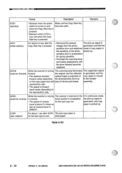
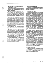
... malfunction of the copier's fixing heater is equipped with a sub thermistor (TH2) to turn off the power supply. CANON PC720/740/7501770 REV.() AUG. 1994 PRINTED IN JAPAN piPoit AU JAPAN) 3 - 51 Checking for the color developing assembly, the...problems associated with the heater is detected during copying operation, the copier once again will indicate `E000' through `E003' is 190°C or less for the black developing assembly or 195°C or less for Overheating at the End of the Fixing Heater The rear end of the fixing heater: a. In multifeeder manual mode...
... malfunction of the copier's fixing heater is equipped with a sub thermistor (TH2) to turn off the power supply. CANON PC720/740/7501770 REV.() AUG. 1994 PRINTED IN JAPAN piPoit AU JAPAN) 3 - 51 Checking for the color developing assembly, the...problems associated with the heater is detected during copying operation, the copier once again will indicate `E000' through `E003' is 190°C or less for the black developing assembly or 195°C or less for Overheating at the End of the Fixing Heater The rear end of the fixing heater: a. In multifeeder manual mode...
Service Manual
Page 101
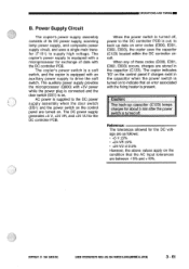
... power supply, scanning lamp power supply, and composite power supply circuit, and uses a single main transfer (T101) to the DC controller PCB is on error codes (E000, E001, E002, E003), the copier uses the capacitor (C123) located within the DC controller circuit. CANON PC720/14017501770 REVD AUG. 1994 PRINTED IN JAPAN ompRat AU JAPON) 3 - 61 When the power switch is turned on . The copier's power switch is a soft switch...
... power supply, scanning lamp power supply, and composite power supply circuit, and uses a single main transfer (T101) to the DC controller PCB is on error codes (E000, E001, E002, E003), the copier uses the capacitor (C123) located within the DC controller circuit. CANON PC720/14017501770 REVD AUG. 1994 PRINTED IN JAPAN ompRat AU JAPON) 3 - 61 When the power switch is turned on . The copier's power switch is a soft switch...
Service Manual
Page 105
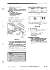
... you are using NB-3. • If you have replaced any of the following parts: • DC controller PCB • Composite power supply PCB • AE/intensity sensor PCB • scanning lamp Preparing for Adjustment 1) Set the black cartridge in the copier. 2) Set the density correction switch (SW101) to the center notch. 0 SW101 Figure 3-701 3) Turn off the AE mechanism, and set the copy density adjusting...
... you are using NB-3. • If you have replaced any of the following parts: • DC controller PCB • Composite power supply PCB • AE/intensity sensor PCB • scanning lamp Preparing for Adjustment 1) Set the black cartridge in the copier. 2) Set the density correction switch (SW101) to the center notch. 0 SW101 Figure 3-701 3) Turn off the AE mechanism, and set the copy density adjusting...
Service Manual
Page 134
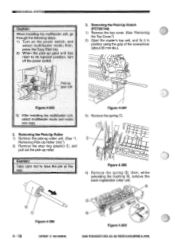
... PRINTED IN JAPAN DMPRIME AU JAPON) O pO Pick-up roller. C.) 4 - 18 Figure 4-306 COPYRIGHT © 1994 CANON INC. Removing the Pick-Up Clutch (PC720/740) 1) Remove the top cover. (See "Removing the Top Cover.") 2) Open the copier's top unit, and fix it in position using the grip of the screwdriver (about 30 mm dia.). 000 0 Figure 4-305 3) After installing the multifeeder unit, select multifeeder mode and make one copy...
... PRINTED IN JAPAN DMPRIME AU JAPON) O pO Pick-up roller. C.) 4 - 18 Figure 4-306 COPYRIGHT © 1994 CANON INC. Removing the Pick-Up Clutch (PC720/740) 1) Remove the top cover. (See "Removing the Top Cover.") 2) Open the copier's top unit, and fix it in position using the grip of the screwdriver (about 30 mm dia.). 000 0 Figure 4-305 3) After installing the multifeeder unit, select multifeeder mode and make one copy...
Service Manual
Page 157
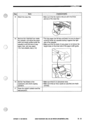
... PRINTED IN JAPAN (INPRIME AU JAPONI 5 - 5 then, set copy paper. • For more details, see p. 5-6. • The copy paper has its face and back; INSTALLATIONM Checks/remarks • Make sure that the copier's ribs are made normally. COPYRIGHT © 1994 CANON INC. be sure to suit the size of the paper width guide. 16 Set the Test Sheet on the copyboard, and check copying operation. 17 Clean the copier...
... PRINTED IN JAPAN (INPRIME AU JAPONI 5 - 5 then, set copy paper. • For more details, see p. 5-6. • The copy paper has its face and back; INSTALLATIONM Checks/remarks • Make sure that the copier's ribs are made normally. COPYRIGHT © 1994 CANON INC. be sure to suit the size of the paper width guide. 16 Set the Test Sheet on the copyboard, and check copying operation. 17 Clean the copier...
Service Manual
Page 158
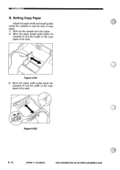
es Figure 5-201 3) Move the paper width guide inside the cassette to suit the length of the copy paper to be used . CANON PC72084017501770 REVD AUG.1994 PRINTEDIN JAPAN oMPRIMt AU JAPON) "'cis e. Figure 5-202 5 - 6 COPYRIGHT © 1994 CANON INC. Setting Copy Paper Adjust the paper width and length guides inside the cassette to suit the size of copy paper. 1) Slide out the cassette from the copier. 2) Move the paper length guide inside the cassette to suit the width of the copy paper to be used . ®INSTALLATION B.
es Figure 5-201 3) Move the paper width guide inside the cassette to suit the length of the copy paper to be used . CANON PC72084017501770 REVD AUG.1994 PRINTEDIN JAPAN oMPRIMt AU JAPON) "'cis e. Figure 5-202 5 - 6 COPYRIGHT © 1994 CANON INC. Setting Copy Paper Adjust the paper width and length guides inside the cassette to suit the size of copy paper. 1) Slide out the cassette from the copier. 2) Move the paper length guide inside the cassette to suit the width of the copy paper to be used . ®INSTALLATION B.
Service Manual
Page 165
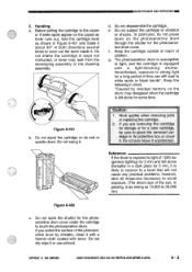
... quickly when removing jams or replacing the cartridge. 2. Do not subject the cartridge to 30,000 lux.) Figure 6-402 c. Reference: If the drum is exposed to light of 1500 lux (general lighting) for a long period of children. MAINTENANCE AND SERVICING 2. Do not disassemble the cartridge. The photosensitive drum is equipped with toner. Do not open the shutter for 5 min, it . Before setting the cartridge to the copier or...
... quickly when removing jams or replacing the cartridge. 2. Do not subject the cartridge to 30,000 lux.) Figure 6-402 c. Reference: If the drum is exposed to light of 1500 lux (general lighting) for a long period of children. MAINTENANCE AND SERVICING 2. Do not disassemble the cartridge. The photosensitive drum is equipped with toner. Do not open the shutter for 5 min, it . Before setting the cartridge to the copier or...


