
Service Manual
Page 2
... BE DIRECTED TO THE COPIER SERVICE DEPARTMENT OF THE SALES COMPANY. Printed in Japan Imprimé au Japon Use of this manual should be strictly supervised to avoid disclosure of confidential information. Prepared by OFFICE IMAGING PRODUCTS TECHNICAL SUPPORT DEPARTMENT 1 OFFICE IMAGING PRODUCTS TECHNICAL SUPPORT DIVISION CANON INC. 5-1, Hakusan 7-chome, Toride-shi, Ibaraki 302 Japan COPYRIGHT © 1998 CANON INC. CANON PC400/420...
... BE DIRECTED TO THE COPIER SERVICE DEPARTMENT OF THE SALES COMPANY. Printed in Japan Imprimé au Japon Use of this manual should be strictly supervised to avoid disclosure of confidential information. Prepared by OFFICE IMAGING PRODUCTS TECHNICAL SUPPORT DEPARTMENT 1 OFFICE IMAGING PRODUCTS TECHNICAL SUPPORT DIVISION CANON INC. 5-1, Hakusan 7-chome, Toride-shi, Ibaraki 302 Japan COPYRIGHT © 1998 CANON INC. CANON PC400/420...

Service Manual
Page 3
..., "Troubleshooting," provides tables of periodically replaced parts and consumables/durables and scheduled servicing charts. CANON PC400/420/430,FC200/220 REV.0 JAN.1998 PRINTED IN JAPAN (IMPRIME AU JAPON) i It also explains the timing at which these units may be disassembled/assembled and adjusted. CHAPTER 8, "Installation," introduces requirements for the following chapters: CHAPTER 1, "General Description," introduces the copier's features and specifications, shows...
..., "Troubleshooting," provides tables of periodically replaced parts and consumables/durables and scheduled servicing charts. CANON PC400/420/430,FC200/220 REV.0 JAN.1998 PRINTED IN JAPAN (IMPRIME AU JAPON) i It also explains the timing at which these units may be disassembled/assembled and adjusted. CHAPTER 8, "Installation," introduces requirements for the following chapters: CHAPTER 1, "General Description," introduces the copier's features and specifications, shows...
Service Manual
Page 5
... Lamp (VR604) ........3-8 2. Outline 3-7 1. Turning the Scanning Lamp COPYRIGHT © 1998 CANON INC. SPECIFICATIONS 1-2 III. Making Copies 1-8 C. Changing the Density ...........1-14 G. Lens Array 1-15 3. Inputs to Replace the Cartridge 1-11 2. Outputs from DC Controller (1/2 2-8 2. Outputs from DC Controller ....2-8 1. EXPOSURE/COPYBOARD DRIVE ON and OFF 3-8 SYSTEM 3-1 2. Outline of Operations (A4, 2 copies 2-3 D. Scanning System 3-10 3. Copyboard Drive Assembly...3-11 A. CANON PC400/420/430,FC200/220 REV.0 JAN.1998 PRINTED...
... Lamp (VR604) ........3-8 2. Outline 3-7 1. Turning the Scanning Lamp COPYRIGHT © 1998 CANON INC. SPECIFICATIONS 1-2 III. Making Copies 1-8 C. Changing the Density ...........1-14 G. Lens Array 1-15 3. Inputs to Replace the Cartridge 1-11 2. Outputs from DC Controller (1/2 2-8 2. Outputs from DC Controller ....2-8 1. EXPOSURE/COPYBOARD DRIVE ON and OFF 3-8 SYSTEM 3-1 2. Outline of Operations (A4, 2 copies 2-3 D. Scanning System 3-10 3. Copyboard Drive Assembly...3-11 A. CANON PC400/420/430,FC200/220 REV.0 JAN.1998 PRINTED...
Service Manual
Page 6
... 6-6 A. CANON PC400/420/430,FC200/220 REV.0 JAN.1998 PRINTED IN JAPAN (IMPRIME AU JAPON) CHAPTER 4 IMAGE FORMATION SYSTEM I . Transfer Charging Control Circuit 4-10 1. Document Density Measurement (AE; Cleaning the Drum...........4-19 B. Transfer Charging Roller.......4-20 1. PC400/FC200 5-3 III. PC420/430/FC220 5-6 2. Delivery Stationary Jam..........5-7 1. Detaching the Pick-Up Roller 5-11 B. Operations 4-4 D. Outline 4-14 2. MECHANICAL SYSTEM............4-18 A. Pick-Up/Feeding Timing Chart (A4, 2 copies...
... 6-6 A. CANON PC400/420/430,FC200/220 REV.0 JAN.1998 PRINTED IN JAPAN (IMPRIME AU JAPON) CHAPTER 4 IMAGE FORMATION SYSTEM I . Transfer Charging Control Circuit 4-10 1. Document Density Measurement (AE; Cleaning the Drum...........4-19 B. Transfer Charging Roller.......4-20 1. PC400/FC200 5-3 III. PC420/430/FC220 5-6 2. Delivery Stationary Jam..........5-7 1. Detaching the Pick-Up Roller 5-11 B. Operations 4-4 D. Outline 4-14 2. MECHANICAL SYSTEM............4-18 A. Pick-Up/Feeding Timing Chart (A4, 2 copies...
Service Manual
Page 8
...-17 7. AC power is too light (dark 4. Pick-Up Assembly..........10-31 2. The copy has poor sharpness 6. The copy has dark lines (paper feed direction, thin 10-19 10. The copy has white lines (paper feed direction).....10-19 12. TROUBLESHOOTING PAPER FEED PROBLEMS 10-30 A. The back of Image Faults ....10-16 IV. The copy is soiled. Checking the Feeding (focus 10-22 Assembly 10-12 21. Fixing/Delivery Assembly 10...
...-17 7. AC power is too light (dark 4. Pick-Up Assembly..........10-31 2. The copy has poor sharpness 6. The copy has dark lines (paper feed direction, thin 10-19 10. The copy has white lines (paper feed direction).....10-19 12. TROUBLESHOOTING PAPER FEED PROBLEMS 10-30 A. The back of Image Faults ....10-16 IV. The copy is soiled. Checking the Feeding (focus 10-22 Assembly 10-12 21. Fixing/Delivery Assembly 10...

Service Manual
Page 13
CHAPTER 1 GENERAL DESCRIPTION I. CANON PC400/420/430,FC200/220 REV.0 JAN.1998 PRINTED IN JAPAN (IMPRIME AU JAPON) 1-1 Auto power-off automatically when left alone for quick copying work. 4. The user need no more than replace the cartridge and perform simple cleaning to black toner, the user has a choice of several colors. Variety of the copier (photosensitive drum, toner case, charging roller, developing assembly, and cleaning assembly) is all...
CHAPTER 1 GENERAL DESCRIPTION I. CANON PC400/420/430,FC200/220 REV.0 JAN.1998 PRINTED IN JAPAN (IMPRIME AU JAPON) 1-1 Auto power-off automatically when left alone for quick copying work. 4. The user need no more than replace the cartridge and perform simple cleaning to black toner, the user has a choice of several colors. Variety of the copier (photosensitive drum, toner case, charging roller, developing assembly, and cleaning assembly) is all...
Service Manual
Page 18
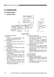
...; CANON PC400/420/430,FC200/220 REV.0 JAN.1998 PRINTED IN JAPAN (IMPRIME AU JAPON) t Copy Count Indicator • Displays the number of paper; ' ' is displayed in response to ' '. y Copy Count Set Key • Each press on the pick-up to 9). • A press while ' ' is switched by self diagnosis. u Clear/Stop Key • During continuous copying, the key serves as a Clear key, setting the copy count to an error...
...; CANON PC400/420/430,FC200/220 REV.0 JAN.1998 PRINTED IN JAPAN (IMPRIME AU JAPON) t Copy Count Indicator • Displays the number of paper; ' ' is displayed in response to ' '. y Copy Count Set Key • Each press on the pick-up to 9). • A press while ' ' is switched by self diagnosis. u Clear/Stop Key • During continuous copying, the key serves as a Clear key, setting the copy count to an error...

Service Manual
Page 19
2. r Main Indicator • Remains ON when copying is ready. CANON PC400/420/430,FC200/220 REV.0 JAN.1998 PRINTED IN JAPAN (IMPRIME AU JAPON) 1-7 PC400/FC200 CHAPTER 1 GENERAL DESCRIPTION 2 lighter darker 1 34 Figure 1-402A q Density Control Lever w Density Indicator e Jam Indicator • Flashes when paper jams inside the copier. • Goes and remains ON when an error (self diagnosis) occurs in the copier. t Power Switch ON OFF 5 (right view) COPYRIGHT © 1998 CANON INC.
2. r Main Indicator • Remains ON when copying is ready. CANON PC400/420/430,FC200/220 REV.0 JAN.1998 PRINTED IN JAPAN (IMPRIME AU JAPON) 1-7 PC400/FC200 CHAPTER 1 GENERAL DESCRIPTION 2 lighter darker 1 34 Figure 1-402A q Density Control Lever w Density Indicator e Jam Indicator • Flashes when paper jams inside the copier. • Goes and remains ON when an error (self diagnosis) occurs in the copier. t Power Switch ON OFF 5 (right view) COPYRIGHT © 1998 CANON INC.
Service Manual
Page 33
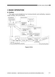
... Primary charging roller Image Formation Block Drum cleaning Photosensitive drum Developing assembly Feeding Copy tray Fixing assembly/Delivery assembly Transfer/ Separation Pick-up control assembly Pick-up tray Pick-up /feeding, exposure, image formation, and control blocks. CANON PC400/420/430,FC200/220 REV.0 JAN.1998 PRINTED IN JAPAN (IMPRIME AU JAPON) 2-1 CHAPTER 2 BASIC OPERATION I. BASIC OPERATION A. Outline The copier can be divided into four functional blocks: pick-up /Feeding Block Figure...
... Primary charging roller Image Formation Block Drum cleaning Photosensitive drum Developing assembly Feeding Copy tray Fixing assembly/Delivery assembly Transfer/ Separation Pick-up control assembly Pick-up tray Pick-up /feeding, exposure, image formation, and control blocks. CANON PC400/420/430,FC200/220 REV.0 JAN.1998 PRINTED IN JAPAN (IMPRIME AU JAPON) 2-1 CHAPTER 2 BASIC OPERATION I. BASIC OPERATION A. Outline The copier can be divided into four functional blocks: pick-up /Feeding Block Figure...
Service Manual
Page 79
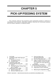
... operation of poweron or when the Copy Start key is pressed 5-9 V. Removing the Separation Pad 5-15 COPYRIGHT © 1998 CANON INC. CONTROLLING THE PICK-UP ROLLER 5-2 A. CANON PC400/420/430,FC200/220 REV.0 JAN.1998 PRINTED IN JAPAN (IMPRIME AU JAPON) 1 Delivery Stationary Jam..........5-7 C. CHAPTER 5 PICK-UP/FEEDING SYSTEM This chapter outlines the machine's pick-up or delivery sensor at time of respective parts. OUTLINE 5-1 II. Pick...
... operation of poweron or when the Copy Start key is pressed 5-9 V. Removing the Separation Pad 5-15 COPYRIGHT © 1998 CANON INC. CONTROLLING THE PICK-UP ROLLER 5-2 A. CANON PC400/420/430,FC200/220 REV.0 JAN.1998 PRINTED IN JAPAN (IMPRIME AU JAPON) 1 Delivery Stationary Jam..........5-7 C. CHAPTER 5 PICK-UP/FEEDING SYSTEM This chapter outlines the machine's pick-up or delivery sensor at time of respective parts. OUTLINE 5-1 II. Pick...

Service Manual
Page 114
... the power switch and door switch are as follows: • +24VR ± 5% • +24 VU : +22 V to prevent damage by overheating the fixing heater. The DC power supply generates +24 V and +5 V. If the microprocessor detects an error on the AC or 24VDC line of the problem, and replace the fuse. CANON PC400/420/430,FC200/220 REV.0 JAN.1998 PRINTED IN...
... the power switch and door switch are as follows: • +24VR ± 5% • +24 VU : +22 V to prevent damage by overheating the fixing heater. The DC power supply generates +24 V and +5 V. If the microprocessor detects an error on the AC or 24VDC line of the problem, and replace the fuse. CANON PC400/420/430,FC200/220 REV.0 JAN.1998 PRINTED IN...

Service Manual
Page 143
... PARTS ........10-34 A. Feeding Faults 10-33 VI. Variable Resistors (VR) and Check Pins by Image Fault 10-17 IV. IMAGE TROUBLESHOOTING 10-11 A. TROUBLESHOOTING MALFUNCTIONS 10-24 A. Switches 10-35 C. MAINTENANCE AND INSPECTION 10-3 A. Image Adjustment Basic Procedure 10-3 B. STANDARDS AND ADJUSTMENTS 10-5 A. Troubleshooting Malfunctions 10-24 V. Copy Paper Jams 10-30 B. SELF DIAGNOSIS 10-40 COPYRIGHT © 1998 CANON INC. CANON PC400...
... PARTS ........10-34 A. Feeding Faults 10-33 VI. Variable Resistors (VR) and Check Pins by Image Fault 10-17 IV. IMAGE TROUBLESHOOTING 10-11 A. TROUBLESHOOTING MALFUNCTIONS 10-24 A. Switches 10-35 C. MAINTENANCE AND INSPECTION 10-3 A. Image Adjustment Basic Procedure 10-3 B. STANDARDS AND ADJUSTMENTS 10-5 A. Troubleshooting Malfunctions 10-24 V. Copy Paper Jams 10-30 B. SELF DIAGNOSIS 10-40 COPYRIGHT © 1998 CANON INC. CANON PC400...

Service Manual
Page 161
... key, and switch the copier OFF in the middle of storage. 2. Re-attach the charging roller. 2. The copy is too light (halftone areas only). 2. Be sure to check quickly to step 5. Is the toner image on the correct method of operation; CHAPTER 10 TROUBLESHOOTING C. YES/NO Remedies YES End. Is the problem corrected? advise the user on the photosensitive drum more or...
... key, and switch the copier OFF in the middle of storage. 2. Re-attach the charging roller. 2. The copy is too light (halftone areas only). 2. Be sure to check quickly to step 5. Is the toner image on the correct method of operation; CHAPTER 10 TROUBLESHOOTING C. YES/NO Remedies YES End. Is the problem corrected? advise the user on the photosensitive drum more or...

Service Manual
Page 162
... of the cartridge. 10-18 COPYRIGHT © 1998 CANON INC. Check if the scanning lamp goes ON normally. 2. CANON PC400/420/430,FC200/220 REV.0 JAN.1998 PRINTED IN JAPAN (IMPRIME AU JAPON) CHAPTER 10 TROUBLESHOOTING 4. Replace the scanning lamp unit. The copy has uneven density (darker at front). Cause Step Checks Scanner 1 Clean the scanning lamp, reflecting plate, and lens. then, open Transfer charging roller the top...
... of the cartridge. 10-18 COPYRIGHT © 1998 CANON INC. Check if the scanning lamp goes ON normally. 2. CANON PC400/420/430,FC200/220 REV.0 JAN.1998 PRINTED IN JAPAN (IMPRIME AU JAPON) CHAPTER 10 TROUBLESHOOTING 4. Replace the scanning lamp unit. The copy has uneven density (darker at front). Cause Step Checks Scanner 1 Clean the scanning lamp, reflecting plate, and lens. then, open Transfer charging roller the top...

Service Manual
Page 163
... 10 TROUBLESHOOTING 7. The copy has white lines (paper feed direction). YES End. 2 Take out the cartridge, and put it back in the middle of toner. YES Remove the foreign matter, or replace the transfer charging roller. COPYRIGHT © 1998 CANON INC. The copy has dark lines (paper feed direction, thin). Cause Step Checks YES/NO Remedies Fixing assembly 1 Press the Copy Start key, and switch the copier OFF in . Is the problem...
... 10 TROUBLESHOOTING 7. The copy has white lines (paper feed direction). YES End. 2 Take out the cartridge, and put it back in the middle of toner. YES Remove the foreign matter, or replace the transfer charging roller. COPYRIGHT © 1998 CANON INC. The copy has dark lines (paper feed direction, thin). Cause Step Checks YES/NO Remedies Fixing assembly 1 Press the Copy Start key, and switch the copier OFF in . Is the problem...

Service Manual
Page 166
... normal? NO Replace the main motor assembly. NO Replace the cartridge. 19. Cause Document Lens Scanner Cartridge Step Checks 1 Does the copy have an image which is found, replace the part. End. The copy has a blurred image. Cause Scanning lamp Cartridge High-voltage transformer Step Checks 1 Does the scanning lamp flicker? 2 Replace the cartridge. Is the problem corrected? CANON PC400/420/430,FC200/220 REV.0 JAN.1998 PRINTED IN JAPAN...
... normal? NO Replace the main motor assembly. NO Replace the cartridge. 19. Cause Document Lens Scanner Cartridge Step Checks 1 Does the copy have an image which is found, replace the part. End. The copy has a blurred image. Cause Scanning lamp Cartridge High-voltage transformer Step Checks 1 Does the scanning lamp flicker? 2 Replace the cartridge. Is the problem corrected? CANON PC400/420/430,FC200/220 REV.0 JAN.1998 PRINTED IN JAPAN...

Service Manual
Page 167
... cartridge. 22. Cause Step Checks 1 Is the scanning lamp ON during copying operation? NO Remove the seal. 4 Set the cartridge in firm contact? Does the drum cover shutter open without fail? CHAPTER 10 TROUBLESHOOTING 21. NO Set the cartridge in the copier? The copy is blank. YES/NO Remedies YES Check if the cartridge is set in the copier. 2 Does the cartridge have toner? CANON PC400/420/430,FC200/220 REV.0 JAN.1998 PRINTED...
... cartridge. 22. Cause Step Checks 1 Is the scanning lamp ON during copying operation? NO Remove the seal. 4 Set the cartridge in firm contact? Does the drum cover shutter open without fail? CHAPTER 10 TROUBLESHOOTING 21. NO Set the cartridge in the copier? The copy is blank. YES/NO Remedies YES Check if the cartridge is set in the copier. 2 Does the cartridge have toner? CANON PC400/420/430,FC200/220 REV.0 JAN.1998 PRINTED...

Service Manual
Page 168
... PCB Fixing assembly Step Checks YES/NO Remedies 1 Set the meter to operate." 3 Switch the copier ON, and make a copy. Measure the voltage between J603-1 (+) and J603-2 (-). Is the voltage lower than that measured in step 1? Check the wiring from the DC controller/DC power supply PCB to the thermistor (TH1); Measure the voltage between J603-1 and J603-2 once again. CANON PC400...
... PCB Fixing assembly Step Checks YES/NO Remedies 1 Set the meter to operate." 3 Switch the copier ON, and make a copy. Measure the voltage between J603-1 (+) and J603-2 (-). Is the voltage lower than that measured in step 1? Check the wiring from the DC controller/DC power supply PCB to the thermistor (TH1); Measure the voltage between J603-1 and J603-2 once again. CANON PC400...

Service Manual
Page 171
... Replace the scanning lamp unit. CANON PC400/420/430,FC200/220 REV.0 JAN.1998 PRINTED IN JAPAN (IMPRIME AU JAPON) 10-27 Does the voltage between J201-6 (+) and J201-7 (-) on the DC controller/DC power supply PCB change to about 24 V at the correct pick-up roller rotate when the door switch is turned ON and the Copy Start key is blocked with paper? 4 Set...
... Replace the scanning lamp unit. CANON PC400/420/430,FC200/220 REV.0 JAN.1998 PRINTED IN JAPAN (IMPRIME AU JAPON) 10-27 Does the voltage between J201-6 (+) and J201-7 (-) on the DC controller/DC power supply PCB change to about 24 V at the correct pick-up roller rotate when the door switch is turned ON and the Copy Start key is blocked with paper? 4 Set...

Service Manual
Page 185
... PCB (faulty) • Control panel PCB (faulty) • DC controller/DC power supply PCB (faulty) • Power supply frequency (error) Description • The copyboard position sensor (Q902) goes ON when copying operation starts. • The copyboard position sensor (Q902) is ON 0.8 sec. Note: 1. CANON PC400/420/430,FC200/220 REV.0 JAN.1998 PRINTED IN JAPAN (IMPRIME AU JAPON) 10-41
... PCB (faulty) • Control panel PCB (faulty) • DC controller/DC power supply PCB (faulty) • Power supply frequency (error) Description • The copyboard position sensor (Q902) goes ON when copying operation starts. • The copyboard position sensor (Q902) is ON 0.8 sec. Note: 1. CANON PC400/420/430,FC200/220 REV.0 JAN.1998 PRINTED IN JAPAN (IMPRIME AU JAPON) 10-41

