
Service Manual
Page 7
...Electrical System 2-82 C. FEATURES 1-1 II. IMAGE FORMATION SYSTEM ..... 2-32 A. Outline of the Electrical System 2-67 B. PARTS OF THE PRINTER 1-8 V. Functions 2-1 B. Scanning System 2-30 IV. Video Controller PCB 2-60 B. OPTION CONTROL SYSTEM ....... 2-64 A. DUPLEXING UNIT ... .... 2-60 A. Paper Jam Detection 2-92 G. Outline 2-42 B. Paper Deck Driver Inputs 2-83 D. Pick-up /Feed System 2-74 E. LASER/SCANNER SYSTEM .......... 2-26 A. BASIC OPERATION 2-1 A. Laser Control Circuit 2-27 C. MAINTENANCE AND SERVICING BY THE CUSTOMER 1-23 VII. Fixing...
...Electrical System 2-82 C. FEATURES 1-1 II. IMAGE FORMATION SYSTEM ..... 2-32 A. Outline of the Electrical System 2-67 B. PARTS OF THE PRINTER 1-8 V. Functions 2-1 B. Scanning System 2-30 IV. Video Controller PCB 2-60 B. OPTION CONTROL SYSTEM ....... 2-64 A. DUPLEXING UNIT ... .... 2-60 A. Paper Jam Detection 2-92 G. Outline 2-42 B. Paper Deck Driver Inputs 2-83 D. Pick-up /Feed System 2-74 E. LASER/SCANNER SYSTEM .......... 2-26 A. BASIC OPERATION 2-1 A. Laser Control Circuit 2-27 C. MAINTENANCE AND SERVICING BY THE CUSTOMER 1-23 VII. Fixing...

Service Manual
Page 9
...4-56 C. Connectors 4-66 IX. Switch/Sensor PCB 4-70 C. Cassette Paper-size Sensing Switch PCB 4-70 D. A-1 II. LOCATION OF ELECTRICAL PARTS/FUNCTION 4-54 A. Envelope Feeder Driver PCB 4-73 G. Option Controller PCB 4-74 H. VARIABLE RESISTORS, LEDS, TEST PINS, JUMPERS, AND SWITCHES ON PC BOARDS ......... 4-69 A. TROUBLESHOOTING 4-47 A. PC Boards 4-64... LIST OF SIGNALS A-7 Incomplete Paper Feed 4-51 VIII. DC Controller PCB 4-69 B. Clutches and Solenoids 4-60 D. Video Controller PCB 4-72 F. Paper Deck Driver PCB 4-75 I . GENERAL CIRCUIT DIAGRAM....
...4-56 C. Connectors 4-66 IX. Switch/Sensor PCB 4-70 C. Cassette Paper-size Sensing Switch PCB 4-70 D. A-1 II. LOCATION OF ELECTRICAL PARTS/FUNCTION 4-54 A. Envelope Feeder Driver PCB 4-73 G. Option Controller PCB 4-74 H. VARIABLE RESISTORS, LEDS, TEST PINS, JUMPERS, AND SWITCHES ON PC BOARDS ......... 4-69 A. TROUBLESHOOTING 4-47 A. PC Boards 4-64... LIST OF SIGNALS A-7 Incomplete Paper Feed 4-51 VIII. DC Controller PCB 4-69 B. Clutches and Solenoids 4-60 D. Video Controller PCB 4-72 F. Paper Deck Driver PCB 4-75 I . GENERAL CIRCUIT DIAGRAM....

Service Manual
Page 54
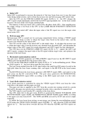
"L" to the VDO signal. Switches the laser on according to switch the laser on when the /LENBL signal and this signal are "L". CHAPTER 2 Laser/scanner unit J1001-9 Laser diode Laser driver -7 -6 -5 -3 -8/-4/-2 -1 J6-3 -2 BD PCB -1 J1-5 -4 -3 Scanner -2 motor -1 DC controller PCB J202-1 -3 -4 -5 -7... DC bias drive signal +24VB -A10/B10 2 - 8 Figure 2-2-5 "L" to adjust the intensity of laser beam is output to forcibly switch the laser on. SCNCLK "L" to intensity of the laser beam. J206-1 -2 -3 /BDI +5V BD input signal (pulse) J18-5 -4 -3 -2 -1 J207...
"L" to the VDO signal. Switches the laser on according to switch the laser on when the /LENBL signal and this signal are "L". CHAPTER 2 Laser/scanner unit J1001-9 Laser diode Laser driver -7 -6 -5 -3 -8/-4/-2 -1 J6-3 -2 BD PCB -1 J1-5 -4 -3 Scanner -2 motor -1 DC controller PCB J202-1 -3 -4 -5 -7... DC bias drive signal +24VB -A10/B10 2 - 8 Figure 2-2-5 "L" to adjust the intensity of laser beam is output to forcibly switch the laser on. SCNCLK "L" to intensity of the laser beam. J206-1 -2 -3 /BDI +5V BD input signal (pulse) J18-5 -4 -3 -2 -1 J207...

Service Manual
Page 67
... side cause an excessive current flow from the video controller. The low-voltage power supply generates the required +24VDC and +5VD for the printer. +24VDC is supplied to the high-voltage power supply PCB to drive the main motor, scanner motor, and fans. +5VDC is used... detection photocoupler DC controller FSRTH RLD /FSRD1E /FSRCT1 /FSRD1 /FSRD1R /FSRD2E /FSRCT2 /FSRD2 /FSRD2R /RLDSNS +24VA /REMT 24 +5V PSTYP +5V Laser driver +5V BD PCB +24VA Scanner motor +24VB High-voltage power supply +24VB Main motor +5V Sensors +24VA Solenoids Clutches +5V Operation panel Switch /sensor...
... side cause an excessive current flow from the video controller. The low-voltage power supply generates the required +24VDC and +5VD for the printer. +24VDC is supplied to the high-voltage power supply PCB to drive the main motor, scanner motor, and fans. +5VDC is used... detection photocoupler DC controller FSRTH RLD /FSRD1E /FSRCT1 /FSRD1 /FSRD1R /FSRD2E /FSRCT2 /FSRD2 /FSRD2R /RLDSNS +24VA /REMT 24 +5V PSTYP +5V Laser driver +5V BD PCB +24VA Scanner motor +24VB High-voltage power supply +24VB Main motor +5V Sensors +24VA Solenoids Clutches +5V Operation panel Switch /sensor...

Service Manual
Page 69
... interface signals (See figure 2-2-15) Video controller PCB DC controller PCB SCANNER MOTOR DRIVE signal (/SCND) LASER DRIVE signal (VDO) Scanner Unit Laser driver Figure 2-2-14 2 - 23 Outline To connect the printer to an external device, such as a host computer, a video controller PCB (interface PCB) is needed. CHAPTER 2 E. This section explains the kinds of...
... interface signals (See figure 2-2-15) Video controller PCB DC controller PCB SCANNER MOTOR DRIVE signal (/SCND) LASER DRIVE signal (VDO) Scanner Unit Laser driver Figure 2-2-14 2 - 23 Outline To connect the printer to an external device, such as a host computer, a video controller PCB (interface PCB) is needed. CHAPTER 2 E. This section explains the kinds of...

Service Manual
Page 71
...rotations period (LSTR). The last rotations operation is switched ON, the printer enters WAIT mode. The video controller receives the /VSREQ signal, and sends the VERTICAL SYNC signal (/VSYNC) to the VDO signal, the laser driver switches the laser diode ON and OFF. The video controller sends the VIDEO signal (...controller to inform it starts the operation of the INTR period, the DC controller sends the VERTICAL SYNC REQUEST signal (/VSREQ) to the laser driver through the face-down or face-up trays. When the /VSYNC signal is received, the print sequence is sent out through the DC ...
...rotations period (LSTR). The last rotations operation is switched ON, the printer enters WAIT mode. The video controller receives the /VSREQ signal, and sends the VERTICAL SYNC signal (/VSYNC) to the VDO signal, the laser driver switches the laser diode ON and OFF. The video controller sends the VIDEO signal (...controller to inform it starts the operation of the INTR period, the DC controller sends the VERTICAL SYNC REQUEST signal (/VSREQ) to the laser driver through the face-down or face-up trays. When the /VSYNC signal is received, the print sequence is sent out through the DC ...

Service Manual
Page 72
...that is aligned by the focusing lens located after the scanning mirror. The laser driver turns the laser diode on and off according to a point of the laser beam (automatic laser power control: See page 2-27). The modulated laser beam is rotating at a constant speed. CHAPTER 2 III. As the ...(/LENBL) from the DC controller is scanned across the drum at a constant speed. LASER/SCANNER SYSTEM A. The drum also rotates at a constant speed allowing the laser beam to the laser driver in the laser/scanner unit. The DC controller then receives the VIDEO signal (VDO) from the video...
...that is aligned by the focusing lens located after the scanning mirror. The laser driver turns the laser diode on and off according to a point of the laser beam (automatic laser power control: See page 2-27). The modulated laser beam is rotating at a constant speed. CHAPTER 2 III. As the ...(/LENBL) from the DC controller is scanned across the drum at a constant speed. LASER/SCANNER SYSTEM A. The drum also rotates at a constant speed allowing the laser beam to the laser driver in the laser/scanner unit. The DC controller then receives the VIDEO signal (VDO) from the video...

Service Manual
Page 73
... Analog adder circuit IC205 J201-C6 /PRNT CPU /RD /WR ADBUS DATA Gate array J201-C1 VDO J201-C16 /BD Laser driver PCB LLCONT J202-2 J1001-8 /LON J202-5 J1001-5 /LENBL J202-4 J1001-6 VDO J202-7 J1001-3 Laser current setting circuit Switching circuit Logic IC PD J202-3 J1001-7 AMP PD (Photo diode...signal by changing the APC1 signal for rough adjustment and APC2 signal for the APC1 signal and APC2 signal at a constant intensity in the laser driver circuit. The VDO signal sent from DA output ports to the analog adder circuit according to the VDO signal when the VIDEO DATA ENABLE...
... Analog adder circuit IC205 J201-C6 /PRNT CPU /RD /WR ADBUS DATA Gate array J201-C1 VDO J201-C16 /BD Laser driver PCB LLCONT J202-2 J1001-8 /LON J202-5 J1001-5 /LENBL J202-4 J1001-6 VDO J202-7 J1001-3 Laser current setting circuit Switching circuit Logic IC PD J202-3 J1001-7 AMP PD (Photo diode...signal by changing the APC1 signal for rough adjustment and APC2 signal for the APC1 signal and APC2 signal at a constant intensity in the laser driver circuit. The VDO signal sent from DA output ports to the analog adder circuit according to the VDO signal when the VIDEO DATA ENABLE...
Service Manual
Page 74
...LON signal is detected by the photo diode (PD). Laser diode emission control Laser diode emission is fed back to the printer and the paper size data. After the CPU sets the FORCED LASER ON signal (/LON) to "L" in the laser/scanner unit. After amplification, the output voltage is ...intensity of the initial APC as the LASER BEAM INTENSITY DETECTION signal (PD). The laser beam emitted from IC205. The laser driver switches the laser ON when the /LENBL and VDO signals are "L". The CPU then sets the FORCED LASER ON signal (/LON) to the laser driver. b. The TOPE and MSK are ...
...LON signal is detected by the photo diode (PD). Laser diode emission control Laser diode emission is fed back to the printer and the paper size data. After the CPU sets the FORCED LASER ON signal (/LON) to "L" in the laser/scanner unit. After amplification, the output voltage is ...intensity of the initial APC as the LASER BEAM INTENSITY DETECTION signal (PD). The laser beam emitted from IC205. The laser driver switches the laser ON when the /LENBL and VDO signals are "L". The CPU then sets the FORCED LASER ON signal (/LON) to the laser driver. b. The TOPE and MSK are ...

Service Manual
Page 76
When the printer is turned ON, the oscillation frequency of a scanner failure in the following cases: a. The CPU on the DC controller becomes "L", the CPU sets the /SCND signal to "L" through the gate array to the scanner driver. Scanning System Figure 2-3-4 shows the scanner motor control circuit. The...(X202) is divided by the gate array (IC205), and the SCNCLK signal is a three-phase, eight-pole DC brushless motor with the scanner driver, which controls the scanner motor rotation at the correct speed. It forms a unit with a HALL element. When the /SCNRDY signal does not ...
When the printer is turned ON, the oscillation frequency of a scanner failure in the following cases: a. The CPU on the DC controller becomes "L", the CPU sets the /SCND signal to "L" through the gate array to the scanner driver. Scanning System Figure 2-3-4 shows the scanner motor control circuit. The...(X202) is divided by the gate array (IC205), and the SCNCLK signal is a three-phase, eight-pole DC brushless motor with the scanner driver, which controls the scanner motor rotation at the correct speed. It forms a unit with a HALL element. When the /SCNRDY signal does not ...

Service Manual
Page 110
...with the video controller and serial communication with the paper deck. OPTION CONTROL SYSTEM A. Outline To use the paper deck installed to the printer, the option controller needs to be attached to the various commands and signals sent from the video controller and signals sent from the ...DC controller. External device (host computer, etc.) Video Controller PCB DC Controller PCB Serial line Option Controller PCB CPU IC101 Serial line Printer Paper deck driver PCB Paper deck Figure 2-7-1 2 - 64 Figure 2-7-2 shows a block diagram of option controller. Option Controller 1.
...with the video controller and serial communication with the paper deck. OPTION CONTROL SYSTEM A. Outline To use the paper deck installed to the printer, the option controller needs to be attached to the various commands and signals sent from the video controller and signals sent from the ...DC controller. External device (host computer, etc.) Video Controller PCB DC Controller PCB Serial line Option Controller PCB CPU IC101 Serial line Printer Paper deck driver PCB Paper deck Figure 2-7-1 2 - 64 Figure 2-7-2 shows a block diagram of option controller. Option Controller 1.

Service Manual
Page 111
... the communication data with the video controller and controls the optional paper deck. CHAPTER 2 2. I/O J102 IC101 I/O CPU BUS IC110 S-RAM IC109 EP-ROM J101 Option driver PCBs (paper deck, etc.) Figure 2-7-2 Video Controller PCB 2 - 65 The CPU communicates with the video controller and the paper deck. CPU (IC101) An NEC 1-chip...
... the communication data with the video controller and controls the optional paper deck. CHAPTER 2 2. I/O J102 IC101 I/O CPU BUS IC110 S-RAM IC109 EP-ROM J101 Option driver PCBs (paper deck, etc.) Figure 2-7-2 Video Controller PCB 2 - 65 The CPU communicates with the video controller and the paper deck. CPU (IC101) An NEC 1-chip...

Service Manual
Page 112
...) constantly stores the latest 40 pages of the paper deck in real time for each page printed to the option controller when the printer power is sent from the DC controller. The option controller sends pick-up source and paper size for each page printed to the ... the option controller sends a power ON (PWRON) signal to the option controller. Operation Outline DC Controller Video Controller PCB PCB Option Controller PCB Paper deck driver PCB Serial line /VSYNC /PDLV /PFED RETURNBACK (GND) CPU (IC101) S-RAM (IC110) +5V GND Serial line PWRON GND Figure 2-7-3 The video controller ...
...) constantly stores the latest 40 pages of the paper deck in real time for each page printed to the option controller when the printer power is sent from the DC controller. The option controller sends pick-up source and paper size for each page printed to the ... the option controller sends a power ON (PWRON) signal to the option controller. Operation Outline DC Controller Video Controller PCB PCB Option Controller PCB Paper deck driver PCB Serial line /VSYNC /PDLV /PFED RETURNBACK (GND) CPU (IC101) S-RAM (IC110) +5V GND Serial line PWRON GND Figure 2-7-3 The video controller ...

Service Manual
Page 113
... notifies the DC controller of signals between the envelope feeder and the printer. The DC controller outputs paper pick-up motor Multi-purpose tray PCB (printer) DC controller PCB (printer) SMT11 J932-1 A -2 /A -3 B -4 /B Motor driver circuit Envelope feeder paper sensor PS931 J931-1 J136-1 J1304-1 +24VA -2 -2 -2 ENVCMD -3 -3 -3 ENVSTS -4 -4... Electrical System The envelope feeder operation sequence is supplied with +24VDC from the printer. CHAPTER 2 VIII. Envelope feeder driver PCB Envelope feeder pick-up commands (1st start, 2nd start) to these commands. The envelope feeder...
... notifies the DC controller of signals between the envelope feeder and the printer. The DC controller outputs paper pick-up motor Multi-purpose tray PCB (printer) DC controller PCB (printer) SMT11 J932-1 A -2 /A -3 B -4 /B Motor driver circuit Envelope feeder paper sensor PS931 J931-1 J136-1 J1304-1 +24VA -2 -2 -2 ENVCMD -3 -3 -3 ENVSTS -4 -4... Electrical System The envelope feeder operation sequence is supplied with +24VDC from the printer. CHAPTER 2 VIII. Envelope feeder driver PCB Envelope feeder pick-up commands (1st start, 2nd start) to these commands. The envelope feeder...

Service Manual
Page 114
...it is rotated counter-clock wise for about 1 second to commands received from the DC controller. DC controller PCB Serial line Envelope feeder driver PCB 1 : ENVELOPE FEEDER PAPER SENSOR signal 1 2 2 : ENVELOPE FEEDER PICK-UP MOTOR DRIVE signals Envelope feeder Torque limiter Envelope feeder... feeder feed roller SMT11 Registration roller Transfer charging roller SMT11: Envelope feeder pick-up and feeds the envelope into the printer. The envelope feeder driver rotates the pick-up /Feed System The envelope feeder motor is a stepping motor (SMT11) that rotates clockwise and ...
...it is rotated counter-clock wise for about 1 second to commands received from the DC controller. DC controller PCB Serial line Envelope feeder driver PCB 1 : ENVELOPE FEEDER PAPER SENSOR signal 1 2 2 : ENVELOPE FEEDER PICK-UP MOTOR DRIVE signals Envelope feeder Torque limiter Envelope feeder... feeder feed roller SMT11 Registration roller Transfer charging roller SMT11: Envelope feeder pick-up and feeds the envelope into the printer. The envelope feeder driver rotates the pick-up /Feed System The envelope feeder motor is a stepping motor (SMT11) that rotates clockwise and ...

Service Manual
Page 117
... registration guide home position sensor PS23 Duplex feed roller 1 home position sensor PS24 CPU IC2002 Duplexing driver PCB Serial line +24VA DC controller PCB Printer SMT21 Switchback motor SMT22 Side registration motor SL21 Switchback roller release solenoid SL22 Duplex deflector solenoid CL21 ... is supplied with +24VDC from the DC controller PCB to control the serial communication between the duplexing unit and the printer are controlled by the duplexing driver PCB. DUPLEXING UNIT A. This PCB utilizes a 4 bit microcomputer (CPU, IC2002) to the duplexing unit and second...
... registration guide home position sensor PS23 Duplex feed roller 1 home position sensor PS24 CPU IC2002 Duplexing driver PCB Serial line +24VA DC controller PCB Printer SMT21 Switchback motor SMT22 Side registration motor SL21 Switchback roller release solenoid SL22 Duplex deflector solenoid CL21 ... is supplied with +24VDC from the DC controller PCB to control the serial communication between the duplexing unit and the printer are controlled by the duplexing driver PCB. DUPLEXING UNIT A. This PCB utilizes a 4 bit microcomputer (CPU, IC2002) to the duplexing unit and second...

Service Manual
Page 118
... when the sensor detects pape J2007-4 -6 -5 +5VB DRHPS "H" when the sensor detects home position of the side registration guide. Duplexing Driver Input Signals Duplexing unit paper sensor PS21 J20-3 -1 -2 Side registration guide home position sensor PS23 J21-3 -1 -2 Switchback sensor PS22 J22-3... -1 -2 Duplex feed roller 1 home position sensor PS24 J23-3 -1 -2 J2008-1 -3 -2 Duplexing driver PCB +5VB /DUPPS "L" when the sensor detects pape J2006-1 -3 -2 +5VB HRHGS "H" when the sensor detects home position of theduplex feed roller ...
... when the sensor detects pape J2007-4 -6 -5 +5VB DRHPS "H" when the sensor detects home position of the side registration guide. Duplexing Driver Input Signals Duplexing unit paper sensor PS21 J20-3 -1 -2 Side registration guide home position sensor PS23 J21-3 -1 -2 Switchback sensor PS22 J22-3... -1 -2 Duplex feed roller 1 home position sensor PS24 J23-3 -1 -2 J2008-1 -3 -2 Duplexing driver PCB +5VB /DUPPS "L" when the sensor detects pape J2006-1 -3 -2 +5VB HRHGS "H" when the sensor detects home position of theduplex feed roller ...

Service Manual
Page 119
... unit. J2004-1 -2 -3 -4 SWBAD SWBAND SWBBD SWBBND Switchback motor control signal J2005-1 -2 -3 -4 -5 -6 HRGCOMA HRGCOMB HRGAD HRGAND HRGBD HRGBND Side registration motor control signal Figure 2-9-3 2 - 73 Duplexing Driver Output Signals Switchback roller release solenoid SL21 Duplex deflector solenoid SL22 Duplex feed cluch CL21 Switchback motor SMT21 Side registration motor SMT22 CHAPTER 2 Duplexing...
... unit. J2004-1 -2 -3 -4 SWBAD SWBAND SWBBD SWBBND Switchback motor control signal J2005-1 -2 -3 -4 -5 -6 HRGCOMA HRGCOMB HRGAD HRGAND HRGBD HRGBND Side registration motor control signal Figure 2-9-3 2 - 73 Duplexing Driver Output Signals Switchback roller release solenoid SL21 Duplex deflector solenoid SL22 Duplex feed cluch CL21 Switchback motor SMT21 Side registration motor SMT22 CHAPTER 2 Duplexing...

Service Manual
Page 120
Once in the duplexing unit the paper is then fed back into the printer by reversing the direction of the paper feed of the switchback roller. The switchback motor (SMT21) is a stepping motor, and can be rotated clock wise ... are driven by the duplex deflector to suit the size of the switchback motor (SMT21). Outline Paper is rotated from the CPU on the duplexing driver PCB. The duplex feed clutch controls the drive of the switchback motor (SMT21) which drives to the switchback unit. CHAPTER 2 D. The switchback roller is guided...
Once in the duplexing unit the paper is then fed back into the printer by reversing the direction of the paper feed of the switchback roller. The switchback motor (SMT21) is a stepping motor, and can be rotated clock wise ... are driven by the duplex deflector to suit the size of the switchback motor (SMT21). Outline Paper is rotated from the CPU on the duplexing driver PCB. The duplex feed clutch controls the drive of the switchback motor (SMT21) which drives to the switchback unit. CHAPTER 2 D. The switchback roller is guided...

Service Manual
Page 121
CHAPTER 2 DC controller PCB Serial line Duplexing driver 1 Switchback roller release plate Switchback roller 2 345 6 SL22 Duplex deflector Fixing delivery roller SL21 PS22 PS23 PS24 7 Fixing rollers Duplex feed roller 1 PS21 89 Second-...
CHAPTER 2 DC controller PCB Serial line Duplexing driver 1 Switchback roller release plate Switchback roller 2 345 6 SL22 Duplex deflector Fixing delivery roller SL21 PS22 PS23 PS24 7 Fixing rollers Duplex feed roller 1 PS21 89 Second-...


