
Parts Manual - Multi
Page 26
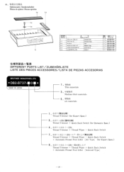
.... 183400- 001 S02738- 001 S02740- 000 S02739- 000 S03816- 001 025050- 236 ftVINIJfil3p- W.* DIFFERENT PARTS LIST/ZUBEHoRLISTE LISTE DES PIECES ACCESSOIRES/LISTA DE PIEZAS ACCESORIAS BROTHER INDUSTRIES, LTD. • DB2-B737- 0 N • MADE IN JAPAN 1 . WW2 Thin materials 3 . a.
.... 183400- 001 S02738- 001 S02740- 000 S02739- 000 S03816- 001 025050- 236 ftVINIJfil3p- W.* DIFFERENT PARTS LIST/ZUBEHoRLISTE LISTE DES PIECES ACCESSOIRES/LISTA DE PIEZAS ACCESORIAS BROTHER INDUSTRIES, LTD. • DB2-B737- 0 N • MADE IN JAPAN 1 . WW2 Thin materials 3 . a.
Network Users Manual - English
Page 2
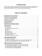
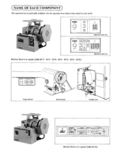
... system 13 ((OPERATION INSTRUCTION 14 Installation of operation box 14 M Motor and control box (Models DB2-B737 • B747 • B748 • B791 • B793 • B795 • B798) 14 0 Operation box (Models DB2-B737 • B747 • B748 • B791 • B793 • B795 • ...B798) 15 ((BLOCK DIAGRAM OF CONTROL CIRCUIT) 18 Ii i Single-phase/100V (Models DB2-6737 • B747 • B791 • B793 • B795 • B798) 18 E Three-phase/200V (Models DB2-B737 • B747 • B791 • B793 • B795 • B798) 19 pi S•...
... system 13 ((OPERATION INSTRUCTION 14 Installation of operation box 14 M Motor and control box (Models DB2-B737 • B747 • B748 • B791 • B793 • B795 • B798) 14 0 Operation box (Models DB2-B737 • B747 • B748 • B791 • B793 • B795 • ...B798) 15 ((BLOCK DIAGRAM OF CONTROL CIRCUIT) 18 Ii i Single-phase/100V (Models DB2-6737 • B747 • B791 • B793 • B795 • B798) 18 E Three-phase/200V (Models DB2-B737 • B747 • B791 • B793 • B795 • B798) 19 pi S•...
Network Users Manual - English
Page 3
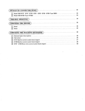
ODETAILS OF CONNECTOR PANEL)) 22 M Model DB2-B737 • B747 • B748 • B791 • B793 • B795 • B798 (Type 300B) 22 Model DB2-B738 (Type #4708) 23 TROUBLESHOOTING 24 CHECKINGTHE MOTOR© 25 111 Motor 25 ri Brake 25 CHECKINGTHE MACHINESOLENOID)S) 26 111 Solenoid load of the machine 26 121 Hem sensor 26 3 B737 Machine control system block diagram 27 4 B738 Machine control system block diagram 28 151 8737 • B738 Motor drive control system block diagram 29
ODETAILS OF CONNECTOR PANEL)) 22 M Model DB2-B737 • B747 • B748 • B791 • B793 • B795 • B798 (Type 300B) 22 Model DB2-B738 (Type #4708) 23 TROUBLESHOOTING 24 CHECKINGTHE MOTOR© 25 111 Motor 25 ri Brake 25 CHECKINGTHE MACHINESOLENOID)S) 26 111 Solenoid load of the machine 26 121 Hem sensor 26 3 B737 Machine control system block diagram 27 4 B738 Machine control system block diagram 28 151 8737 • B738 Motor drive control system block diagram 29
Network Users Manual - English
Page 4
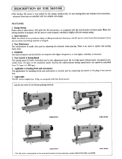
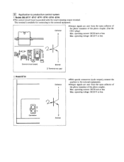
...Sewing Speed The sewing speed is best suited for the following sewing machines. [DB2-B7371 4 ,7 [DB2-6738] 4 [DB2-67911 *The DC motor is no need to the automatic thread trimming machines, models DB2-6748, 8795, and 8798. [DB2-B793] There is also applied to replace the moving brake plate. 4. ... the sewing machine is stopped, the DC motor is controlled from 215 spm to the maximum speed. ©DESCRIPTION OF THE MOTOR *The Brother DC motor is freely controlled just by the adjustment knob. Free Control of the control box. 7. To save sewing labor and enhance the ...
...Sewing Speed The sewing speed is best suited for the following sewing machines. [DB2-B7371 4 ,7 [DB2-6738] 4 [DB2-67911 *The DC motor is no need to the automatic thread trimming machines, models DB2-6748, 8795, and 8798. [DB2-B793] There is also applied to replace the moving brake plate. 4. ... the sewing machine is stopped, the DC motor is controlled from 215 spm to the maximum speed. ©DESCRIPTION OF THE MOTOR *The Brother DC motor is freely controlled just by the adjustment knob. Free Control of the control box. 7. To save sewing labor and enhance the ...
Network Users Manual - English
Page 5
... ED Operation Box E-2 brother E-4 -4 • il El 0 All \ ,I c T , A 8 C O I I O Synchronizer 0 0 t -rT-r1 Treadle Unit bEoXEtDhReA r• PROGRAMMING SET Favr r 2PRODOMOIE 3 4 MONITOR CrFIECTION A B C D CORRECTION MEE 0000 +0.5 1.51, . 4e1 411 Machine Head to be Applied [DB2-B738] t0 RIO@EIMORI El m './ X V V se ES D C ID N ea I Operation Box E-4 Machine Head to be Applied [DB2-B737 • B747 •...
... ED Operation Box E-2 brother E-4 -4 • il El 0 All \ ,I c T , A 8 C O I I O Synchronizer 0 0 t -rT-r1 Treadle Unit bEoXEtDhReA r• PROGRAMMING SET Favr r 2PRODOMOIE 3 4 MONITOR CrFIECTION A B C D CORRECTION MEE 0000 +0.5 1.51, . 4e1 411 Machine Head to be Applied [DB2-B738] t0 RIO@EIMORI El m './ X V V se ES D C ID N ea I Operation Box E-4 Machine Head to be Applied [DB2-B737 • B747 •...
Network Users Manual - English
Page 9
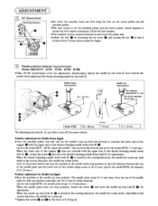
... machine pulley and the motor pulley, which happens to loosen the belt tension sometimes. Synchronizer detects the needle by finger. 2 Needle position detector (synchronizer) Model DB2-B747 • B791 • B793 • B795 • B798 *Take off the power switch. 0 Position Adjustment for Needle Down Signal *Turn the machine pulley this...
... machine pulley and the motor pulley, which happens to loosen the belt tension sometimes. Synchronizer detects the needle by finger. 2 Needle position detector (synchronizer) Model DB2-B747 • B791 • B793 • B795 • B798 *Take off the power switch. 0 Position Adjustment for Needle Down Signal *Turn the machine pulley this...
Network Users Manual - English
Page 10
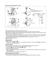
... 0.5 mm clearance between needle plate top and needle set screws 0 in the down position, the distance between the pulley bottom and the synchro- Synchronizer Model DB2-B737 • B748 Higher Lower Lower Higher 0 Needle up stop Thin, regular materials: 10 ^ 12 mm Thick materials: 10 --14 mm Reference line 0 Needle down stop...
... 0.5 mm clearance between needle plate top and needle set screws 0 in the down position, the distance between the pulley bottom and the synchro- Synchronizer Model DB2-B737 • B748 Higher Lower Lower Higher 0 Needle up stop Thin, regular materials: 10 ^ 12 mm Thick materials: 10 --14 mm Reference line 0 Needle down stop...
Network Users Manual - English
Page 11
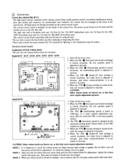
... volume knobs with one -stitich modification switch, slow start switch and connector for synchronizer and connector for lighting, or the transformer may be broken. Model B737 • B747 • B748 • B791 • B793 • B795 • B798 [-inn r lu 0 VR3 VR2 nn 11 E L_I LJ 0 I LCVR SVR O 0 0...3: When any volume knob is changed by finger because high voltage is furnished with great care. 131 Control box Control Box (Model DB2-B737) The high speed volume, backtack stitch volume, power lamp, needle position switch, one 15A fuse for the 110-240V single-phase ...
... volume knobs with one -stitich modification switch, slow start switch and connector for synchronizer and connector for lighting, or the transformer may be broken. Model B737 • B747 • B748 • B791 • B793 • B795 • B798 [-inn r lu 0 VR3 VR2 nn 11 E L_I LJ 0 I LCVR SVR O 0 0...3: When any volume knob is changed by finger because high voltage is furnished with great care. 131 Control box Control Box (Model DB2-B737) The high speed volume, backtack stitch volume, power lamp, needle position switch, one 15A fuse for the 110-240V single-phase ...
Network Users Manual - English
Page 15
m 000 320 11:111-1 (0/ •=o7 111111- -cp CI Control circuit board 1 Emitter 2 Terminal not used 2. operating voltage: DC20 V or less 2 1 Connector 2 Emitter Models DB2-B737 • B747 • B791 • B793. operating current: DC20 mA or less Max. B795- This terminal is procided with the tread trimming output terminal. Collector 3 *...
m 000 320 11:111-1 (0/ •=o7 111111- -cp CI Control circuit board 1 Emitter 2 Terminal not used 2. operating voltage: DC20 V or less 2 1 Connector 2 Emitter Models DB2-B737 • B747 • B791 • B793. operating current: DC20 mA or less Max. B795- This terminal is procided with the tread trimming output terminal. Collector 3 *...
Network Users Manual - English
Page 16
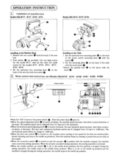
... needle up to the needle down position. Fix the mounting plate 0 on the back of operation box Models DB2-B737 • B747 • B748 • B791 • • :g• Models DB2-B793 • B795- And when counterclockwise, it decreases. clockwise, it decreases. The start and continuous backtack ...position and the machine is turned on the back of the power switch 0 . And use (Models DB2-B737 • B747 • B748 • B791 • B795 • B798) Power switch O0 a 11 brother 0©000 *Push the "ON" button of the arm bed with the machine stopped, the ...
... needle up to the needle down position. Fix the mounting plate 0 on the back of operation box Models DB2-B737 • B747 • B748 • B791 • • :g• Models DB2-B793 • B795- And when counterclockwise, it decreases. clockwise, it decreases. The start and continuous backtack ...position and the machine is turned on the back of the power switch 0 . And use (Models DB2-B737 • B747 • B748 • B791 • B795 • B798) Power switch O0 a 11 brother 0©000 *Push the "ON" button of the arm bed with the machine stopped, the ...
Network Users Manual - English
Page 17
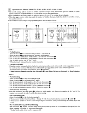
... of stitches N can be changed during the fixed stitch sewing can be executed after setting as E-2. The number of stitches for the fixed stitch sewing N. 2. brother E-2 0 II II -l t d 0 DI i Al031 Aid & LY 0 O LA EOE 0 0 0 0000 ro 6 bmEt-h4er 1-- o For Half Stitch Switch... O For Fixed Stitch Sewing and Thread Trimming With the switch 0 pressed, the fixed stitch sewing is stopped with the counter 0. 5. 3 Operation box (Models DB2-B737 • B747 • B791 • B793 • B795 • B798) *The switch settings and the number of stitches cannot be set using the ...
... of stitches N can be changed during the fixed stitch sewing can be executed after setting as E-2. The number of stitches for the fixed stitch sewing N. 2. brother E-2 0 II II -l t d 0 DI i Al031 Aid & LY 0 O LA EOE 0 0 0 0000 ro 6 bmEt-h4er 1-- o For Half Stitch Switch... O For Fixed Stitch Sewing and Thread Trimming With the switch 0 pressed, the fixed stitch sewing is stopped with the counter 0. 5. 3 Operation box (Models DB2-B737 • B747 • B791 • B793 • B795 • B798) *The switch settings and the number of stitches cannot be set using the ...
Network Users Manual - English
Page 24
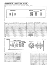
... CI III AC ©00M Ac El CI 0 El Front face of Control box 5A 5A FUSE FUSE Fuse Motor Power gi O w Synchronizer Operation box B737 ®r© (Note) 380 V-440 V 3 A Motor No. 6P connector 1 Vf. TH 4 Motor + 5 Vf 6 Motor - Synchronizer 1 GND 2 DC + 5 ...V 3 Needle down 4 0 V 5 NO. TH 3 if. .DETAILS OF CONNECTOR PANEL 1 Model DB2-B737 • B747 • B748 • B791 • B793 • B795 • B798 (Type 3O0B) For standing work O th` 0 CD CD Machine head Presser foot lifter...
... CI III AC ©00M Ac El CI 0 El Front face of Control box 5A 5A FUSE FUSE Fuse Motor Power gi O w Synchronizer Operation box B737 ®r© (Note) 380 V-440 V 3 A Motor No. 6P connector 1 Vf. TH 4 Motor + 5 Vf 6 Motor - Synchronizer 1 GND 2 DC + 5 ...V 3 Needle down 4 0 V 5 NO. TH 3 if. .DETAILS OF CONNECTOR PANEL 1 Model DB2-B737 • B747 • B748 • B791 • B793 • B795 • B798 (Type 3O0B) For standing work O th` 0 CD CD Machine head Presser foot lifter...

Network Users Manual - English
Page 25
... No. SYC 5 SCAN 5 15 LSCAN 1 6 GND 6 SCAN 6 16 LSCAN 2 7 Needle up 7 SCAN 3 17 PC 1 8 Encoder 8 SCAN 4 18 PC 2 9 SCAN 1 19 DC+ 5 V 10 SCAN 2 20 0 V 2 Model DB2-B738 (Type #47OB) Potentiometer Cycle output 2 Needle position switch Hem detection O Correction C)SC) 00C) switch ArT\ \Li 0 0 0 For standing work Machine head Brake scp() Presser...
... No. SYC 5 SCAN 5 15 LSCAN 1 6 GND 6 SCAN 6 16 LSCAN 2 7 Needle up 7 SCAN 3 17 PC 1 8 Encoder 8 SCAN 4 18 PC 2 9 SCAN 1 19 DC+ 5 V 10 SCAN 2 20 0 V 2 Model DB2-B738 (Type #47OB) Potentiometer Cycle output 2 Needle position switch Hem detection O Correction C)SC) 00C) switch ArT\ \Li 0 0 0 For standing work Machine head Brake scp() Presser...


