
Cap to Tubular - English
Page 1
... thumb screw (G) and slide the guide bar (F) out of the lower arm. 3) Remove the two short black thumb screws, inner ones, (E) and remove the cap driver from the machine by sliding it toward you. 4) Remove the two long black thumb screws (D) and remove the metal bar with the "L" stamped into the...
... thumb screw (G) and slide the guide bar (F) out of the lower arm. 3) Remove the two short black thumb screws, inner ones, (E) and remove the cap driver from the machine by sliding it toward you. 4) Remove the two long black thumb screws (D) and remove the metal bar with the "L" stamped into the...

Tubular to Cap - English
Page 1
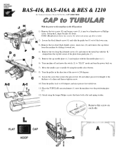
... (E). 12) Swing the "L" shaped plate (H) up behind the pantograph. 13) Attach the two screws (K). Secure with the long black thumbscrews (D). 9) Slide the cap driver attachment through the sewing arm of the machine. 10) Slide the guide bar (F) into the hole to the rear of the arm until it has..." mode and turn the power back on. 4) Move the needle case to needle #1 using cap drive system, also please use the proper screws. BAS-416, BAS-416A & BES-1210 For Technical Assistance Please Call Toll Free 1-877-4BROTHER Remove this screw please be sure it stops 11) Tighten the black thumb knob...
... (E). 12) Swing the "L" shaped plate (H) up behind the pantograph. 13) Attach the two screws (K). Secure with the long black thumbscrews (D). 9) Slide the cap driver attachment through the sewing arm of the machine. 10) Slide the guide bar (F) into the hole to the rear of the arm until it has..." mode and turn the power back on. 4) Move the needle case to needle #1 using cap drive system, also please use the proper screws. BAS-416, BAS-416A & BES-1210 For Technical Assistance Please Call Toll Free 1-877-4BROTHER Remove this screw please be sure it stops 11) Tighten the black thumb knob...
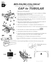
Cap to Tubular - English
Page 1
... screw (G) and slide the guide bar (F) out of the lower arm. 3) Remove the two short black thumb screws, inner ones, (E) and remove the cap driver from the machine by sliding it toward you. 4) Remove the two long black thumb screws (D) and remove the metal bar with the "L" stamped into the... the switch (L) to the machine in the ON position. 1) Remove the two screws (K) and loosen screw (J), it may be a thumbscrew or Phillips screw. BAS-416, BAS-416A & BES & 1210 For Technical Assistance Please Call Toll Free 1-877-4BROTHER With the power to "FLAT" mode and turn the power back on each side
... screw (G) and slide the guide bar (F) out of the lower arm. 3) Remove the two short black thumb screws, inner ones, (E) and remove the cap driver from the machine by sliding it toward you. 4) Remove the two long black thumb screws (D) and remove the metal bar with the "L" stamped into the... the switch (L) to the machine in the ON position. 1) Remove the two screws (K) and loosen screw (J), it may be a thumbscrew or Phillips screw. BAS-416, BAS-416A & BES & 1210 For Technical Assistance Please Call Toll Free 1-877-4BROTHER With the power to "FLAT" mode and turn the power back on each side

Instruction Manual - English
Page 19
... during standstill or pause. • The needle thread take -ups are in a horizontal line. Do not release it must be off the power. 2. BAS-416A • BES-1,210AC 9 * The proper needle bar stop position is proper when turning on the power and when reopening to sew during restarting carriages X ... ordinary operation after turning on the power. If the needle bar in the sewing position is down, it . 3. To separate them, insert a screw driver in the sewing position, should form a horizontal line. • All the needle bars, including the needle bar in the gap according to the highest ...
... during standstill or pause. • The needle thread take -ups are in a horizontal line. Do not release it must be off the power. 2. BAS-416A • BES-1,210AC 9 * The proper needle bar stop position is proper when turning on the power and when reopening to sew during restarting carriages X ... ordinary operation after turning on the power. If the needle bar in the sewing position is down, it . 3. To separate them, insert a screw driver in the sewing position, should form a horizontal line. • All the needle bars, including the needle bar in the gap according to the highest ...
Parts Manual - English
Page 87
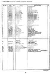
xisA FUSE, 15A 6 142443001 1 * :7.7 7 .iz 1.9X52 SCREW DRIVER, 1.9X52 7 118837001 1 4, -)*7 7 :>3.4X70 SCREW DRIVER, 3.4X70 8 101572101 1 * )".7 7 5/ 5.5X190 SCREW DRIVER, 5.5X190 9 150332001 1 7°5a i:7 1n-NO.2 DRIVER, NO.2 10 150335001 1 6/7/*rayAivj-5 HEXAGONAL WRENCH, 5 11 118064001 1 611h*rj) aitt4 HEXAGONAL WRENCH,....NO. xsAsT FUSE, 5AST 2-2 502887000 1 ea- a h .% h 30 GREASE TUNK, 30 26 508170001 1 zii9*:279?, SCREW DRIVER, z-STEEL 28 536461001 1 )0, >5•-:-IL, -- BOTTOM DEAD CENTER GAUGE 46 532656001 1 -f₹lx/ CODE Q'TY E .1,.
xisA FUSE, 15A 6 142443001 1 * :7.7 7 .iz 1.9X52 SCREW DRIVER, 1.9X52 7 118837001 1 4, -)*7 7 :>3.4X70 SCREW DRIVER, 3.4X70 8 101572101 1 * )".7 7 5/ 5.5X190 SCREW DRIVER, 5.5X190 9 150332001 1 7°5a i:7 1n-NO.2 DRIVER, NO.2 10 150335001 1 6/7/*rayAivj-5 HEXAGONAL WRENCH, 5 11 118064001 1 611h*rj) aitt4 HEXAGONAL WRENCH,....NO. xsAsT FUSE, 5AST 2-2 502887000 1 ea- a h .% h 30 GREASE TUNK, 30 26 508170001 1 zii9*:279?, SCREW DRIVER, z-STEEL 28 536461001 1 )0, >5•-:-IL, -- BOTTOM DEAD CENTER GAUGE 46 532656001 1 -f₹lx/ CODE Q'TY E .1,.


