
Maintenance Schedule - English
Page 1
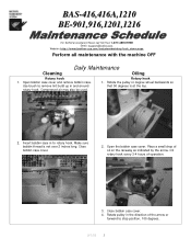
... build up in to rotary hook. Compressed air may also be used. Rotary hook 1. BAS-416,416A,1210 BE-901,916,1201,1216 For Technical Assistance Please Call Toll Fre e 1-877-4BROTHER Email: tsupport@brother.com Website: http://www.brother-usa.com/industembroidery/tech_down.aspx Perform all maintenance with the machine OFF Daily Maintenance Cleaning...
... build up in to rotary hook. Compressed air may also be used. Rotary hook 1. BAS-416,416A,1210 BE-901,916,1201,1216 For Technical Assistance Please Call Toll Fre e 1-877-4BROTHER Email: tsupport@brother.com Website: http://www.brother-usa.com/industembroidery/tech_down.aspx Perform all maintenance with the machine OFF Daily Maintenance Cleaning...
Maintenance Schedule - English
Page 2
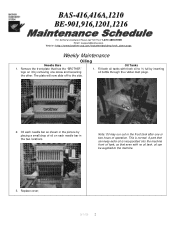
... can keep extra oil is normal. A part that has the "BROTHER" logo on each needle bar as shown in the front tank after one screw and loosening the other. Replace cover. 9/1/05 2 BAS-416,416A,1210 BE-901,916,1201,1216 For Technical Assistance Please Call Toll ...Fre e 1-877-4BROTHER Email: tsupport@brother.com Website: http://www.brother-usa.com/industembroidery/tech_down.aspx Weekly Maintenance Oiling Needle Bars 1. Remove ...
... can keep extra oil is normal. A part that has the "BROTHER" logo on each needle bar as shown in the front tank after one screw and loosening the other. Replace cover. 9/1/05 2 BAS-416,416A,1210 BE-901,916,1201,1216 For Technical Assistance Please Call Toll ...Fre e 1-877-4BROTHER Email: tsupport@brother.com Website: http://www.brother-usa.com/industembroidery/tech_down.aspx Weekly Maintenance Oiling Needle Bars 1. Remove ...
Maintenance Schedule - English
Page 3
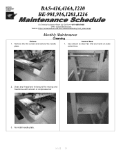
Clean any thread and lint around the moving and fixed knive with a brush or compressed air 3. Remove the two screws and remove the needle plate. Use a brush to clean fan inlet and vents on sides control box. 2. BAS-416,416A,1210 BE-901,916,1201,1216 For Technical Assistance Please Call Toll Fre e 1-877-4BROTHER Email: tsupport@brother.com Website: http://www.brother-usa.com/industembroidery/tech_down.aspx Monthly Maintenance Cleaning Knives 1. Re-install needle plate. 9/1/05 3 Control Box 1.
Clean any thread and lint around the moving and fixed knive with a brush or compressed air 3. Remove the two screws and remove the needle plate. Use a brush to clean fan inlet and vents on sides control box. 2. BAS-416,416A,1210 BE-901,916,1201,1216 For Technical Assistance Please Call Toll Fre e 1-877-4BROTHER Email: tsupport@brother.com Website: http://www.brother-usa.com/industembroidery/tech_down.aspx Monthly Maintenance Cleaning Knives 1. Re-install needle plate. 9/1/05 3 Control Box 1.
Maintenance Schedule - English
Page 4
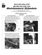
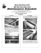
... the left . Apply black grease (BR2) to the grease (30) to the roller bearings. BAS-416,416A,1210 BE-901,916,1201,1216 For Technical As sistance Please Call Toll Free 1-877-4BROTHER Email: tsupport@brother.com Website: http://www.brother-usa.com/industembroidery/tech_down.aspx 6 Month Maintenance Greasing Color Change Assembly Color Change Linear...
... the left . Apply black grease (BR2) to the grease (30) to the roller bearings. BAS-416,416A,1210 BE-901,916,1201,1216 For Technical As sistance Please Call Toll Free 1-877-4BROTHER Email: tsupport@brother.com Website: http://www.brother-usa.com/industembroidery/tech_down.aspx 6 Month Maintenance Greasing Color Change Assembly Color Change Linear...
Maintenance Schedule - English
Page 5
... right side. 2. Apply white grease (30) to the two grooves of the machine. 9/1/05 5 BAS-416,416A,1210 BE-901,916,1201,1216 For Technical Assistance Please Call Toll Fre e 1-877-4BROTHER Email: tsupport@brother.com Website: http://www.brother-usa.com/industembroidery/tech_down.aspx 6 Month Maintenance Greasing X Linear Rail Y Linear Rails 1. This will 1. Apply...
... right side. 2. Apply white grease (30) to the two grooves of the machine. 9/1/05 5 BAS-416,416A,1210 BE-901,916,1201,1216 For Technical Assistance Please Call Toll Fre e 1-877-4BROTHER Email: tsupport@brother.com Website: http://www.brother-usa.com/industembroidery/tech_down.aspx 6 Month Maintenance Greasing X Linear Rail Y Linear Rails 1. This will 1. Apply...
Maintenance Schedule - English
Page 6
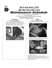
BAS-416,416A,1210 BE-901,916,1201,1216 For Technical Assistance Please Call Toll Fre e 1-877-4BROTHER Email: tsupport@brother.com Website: http://www.brother-usa.com/industembroidery/tech_down.aspx 6 Month Maintenance Greasing Oiling Presser Foot Assembly 1. Color change the machine to the grooves of the presser foot guide plate ...
BAS-416,416A,1210 BE-901,916,1201,1216 For Technical Assistance Please Call Toll Fre e 1-877-4BROTHER Email: tsupport@brother.com Website: http://www.brother-usa.com/industembroidery/tech_down.aspx 6 Month Maintenance Greasing Oiling Presser Foot Assembly 1. Color change the machine to the grooves of the presser foot guide plate ...
Changing Needle Bar Cushions - English
Page 1
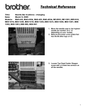
changing Date: March 5, 2009 Models: BAS-416, BAS-416A, BAS-423, BAS-423A, BE-0901, BE-1201, BES-916, BES-1216, BES-1230, BES-1210, BES-1240, BES-1241, BES-1260, BES-1261, BES- 1262, BES-1263, BES-960, BES-961 1. Technical Reference Title: Needle Bar Cushions - Loosen Top Dead Center Stopper screw with a 2.5mm hex wrench on it). 3. Remove the lower cover (plate that has the Brother logo on all the needles. 1 Move the needle case to the highest needle bar number (9 or 12 depending on your model). 2.
changing Date: March 5, 2009 Models: BAS-416, BAS-416A, BAS-423, BAS-423A, BE-0901, BE-1201, BES-916, BES-1216, BES-1230, BES-1210, BES-1240, BES-1241, BES-1260, BES-1261, BES- 1262, BES-1263, BES-960, BES-961 1. Technical Reference Title: Needle Bar Cushions - Loosen Top Dead Center Stopper screw with a 2.5mm hex wrench on it). 3. Remove the lower cover (plate that has the Brother logo on all the needles. 1 Move the needle case to the highest needle bar number (9 or 12 depending on your model). 2.
Quick Reference Guide - English
Page 1
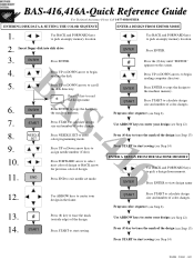
... UP or DOWN arrows to calculate design size and number of the design. START Press START to begin reading the disk. ENTER BA* ENTER S START NEEDLE -416 SET Press ENTER. Press UP or DOWN arrow to the machine memory. Press ENTER to copy the design to begin reading computer ...see Step 13) Press START to start sewing (see Step 14) FO/SB - 2000/1 - 002 Press NEEDLE SET to exit needle set mode. BAS-416,416A-Quick Reference Guide For Technical Assistance Please Call 1-877-4BROTHER ENTERING DISK DATA & SETTING THE COLOR SEQUENCE ENTER A DESIGN FROM EDITOR MODE 1. END Press ...
... UP or DOWN arrows to calculate design size and number of the design. START Press START to begin reading the disk. ENTER BA* ENTER S START NEEDLE -416 SET Press ENTER. Press UP or DOWN arrow to the machine memory. Press ENTER to copy the design to begin reading computer ...see Step 13) Press START to start sewing (see Step 14) FO/SB - 2000/1 - 002 Press NEEDLE SET to exit needle set mode. BAS-416,416A-Quick Reference Guide For Technical Assistance Please Call 1-877-4BROTHER ENTERING DISK DATA & SETTING THE COLOR SEQUENCE ENTER A DESIGN FROM EDITOR MODE 1. END Press ...
Tubular to Cap - English
Page 1
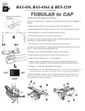
... locator pins (C). Other screws can cause mechanical problems. 14) Tighten the phillips or thumb screw (J) located on it has both a spring washer and flat washer. BAS-416, BAS-416A & BES-1210 For Technical Assistance Please Call Toll Free 1-877-4BROTHER Remove this screw please be sure it , and secure with the "L" stamped on the...
... locator pins (C). Other screws can cause mechanical problems. 14) Tighten the phillips or thumb screw (J) located on it has both a spring washer and flat washer. BAS-416, BAS-416A & BES-1210 For Technical Assistance Please Call Toll Free 1-877-4BROTHER Remove this screw please be sure it , and secure with the "L" stamped on the...

Cap to Tubular - English
Page 1
BAS-416, BAS-416A & BES & 1210 For Technical Assistance Please Call Toll Free 1-877-4BROTHER With the power to the machine in the ON position. 1) Remove the two screws (K) ...
BAS-416, BAS-416A & BES & 1210 For Technical Assistance Please Call Toll Free 1-877-4BROTHER With the power to the machine in the ON position. 1) Remove the two screws (K) ...

Service Manual
Page 1
BES-1210AC SERVICE MANUAL BAS-401, 412A, 416A Please read this manual before making any adjustments. SINGLE HEAD ELECTRONIC EMBROIDERY MACHINE
BES-1210AC SERVICE MANUAL BAS-401, 412A, 416A Please read this manual before making any adjustments. SINGLE HEAD ELECTRONIC EMBROIDERY MACHINE
Service Manual
Page 3
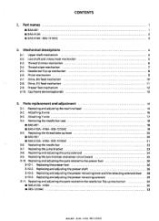
... CONTENTS 1. Needle bar flip-up lever 20 ■ BAS-401 20 ■ BAS-412A • 416A • BES-1210AC 21 3-6. Removing the needle bar case 18 ■ BAS-401 18 ■ BAS-412A • 416A • BES-1210AC 19 3-5. Replacing and adjusting the ...parts related to the needle bar flip-up mechanism 30 ■ BAS-412A • 416A 30 ■ BES-1210AC 33 BAS-401 412A• 416A- Attaching Y wire 17 3-4. Replacing and adjusting the presser shaft 26 3-10-3. Mechanical descriptions 4 2-1. Picker...
... CONTENTS 1. Needle bar flip-up lever 20 ■ BAS-401 20 ■ BAS-412A • 416A • BES-1210AC 21 3-6. Removing the needle bar case 18 ■ BAS-401 18 ■ BAS-412A • 416A • BES-1210AC 19 3-5. Replacing and adjusting the ...parts related to the needle bar flip-up mechanism 30 ■ BAS-412A • 416A 30 ■ BES-1210AC 33 BAS-401 412A• 416A- Attaching Y wire 17 3-4. Replacing and adjusting the presser shaft 26 3-10-3. Mechanical descriptions 4 2-1. Picker...

Service Manual
Page 4
... the fixed knife 43 4-8. SOL (solenoid) function 61 5-3-7. Adjusting the presser foot height 40 4-3-1. Adjusting the spring 41 • BAS-401 41 ■ BAS-412A • 416A • BES-1210AC 41 4-5. Replacing an adjusting the potentiometer assembly 49 4-14. Positioning the bobbin presser 51 5. Adjusting the position... Travel function 54 5-3-3. Memory function 55 5-34. Y-feed wire 46 4-10. Adjusting the bobbin winder 51 4-14-1. Test mode 52 • BAS-412A 52 5-1. X-feed wire 45 4-9-2. Adjusting the thread sensor 48 ■...
... the fixed knife 43 4-8. SOL (solenoid) function 61 5-3-7. Adjusting the presser foot height 40 4-3-1. Adjusting the spring 41 • BAS-401 41 ■ BAS-412A • 416A • BES-1210AC 41 4-5. Replacing an adjusting the potentiometer assembly 49 4-14. Positioning the bobbin presser 51 5. Adjusting the position... Travel function 54 5-3-3. Memory function 55 5-34. Y-feed wire 46 4-10. Adjusting the bobbin winder 51 4-14-1. Test mode 52 • BAS-412A 52 5-1. X-feed wire 45 4-9-2. Adjusting the thread sensor 48 ■...

Service Manual
Page 5
...the flat hoop stoppers (only possible in flat mode) 83 ■ BAS-401 • 416A • BES-1210AC 84 5-9-5. Replacing the circuit boards 92 7-3. LCD module assembly 99 BAS-401- 412A • 416A- Port function 69 5-7. Adjusting the cap frame overtravel sensor 82 5-9-4. ...63 5-6. Explanations of test mode functions 64 5-6-1. Adjusting the flat hoop stoppers (only possible in flat mode) 86 6. ■ BAS-401 • 416A • BES-1210AC 63 5-4. Replacing the power supply circuit board 94 7-5. Starting the test mode 63 5-5. SOL. (solenoid) ...
...the flat hoop stoppers (only possible in flat mode) 83 ■ BAS-401 • 416A • BES-1210AC 84 5-9-5. Replacing the circuit boards 92 7-3. LCD module assembly 99 BAS-401- 412A • 416A- Port function 69 5-7. Adjusting the cap frame overtravel sensor 82 5-9-4. ...63 5-6. Explanations of test mode functions 64 5-6-1. Adjusting the flat hoop stoppers (only possible in flat mode) 86 6. ■ BAS-401 • 416A • BES-1210AC 63 5-4. Replacing the power supply circuit board 94 7-5. Starting the test mode 63 5-5. SOL. (solenoid) ...

Service Manual
Page 7
... problem 144 9-2. Error messages 148 ■ BAS-412A 148 ■ BAS-401 • 416A • BES-1210AC 151 BAS-401 • 416A • BES-1210AC Keyboard unit control block diagram 154 BAS-412A Keyboard unit control block diagram 155 BAS-401 Control block diagram 156 BAS-412A Control block diagram 157 BAS-416A Control block diagram 158 BES-1210AC Control...
... problem 144 9-2. Error messages 148 ■ BAS-412A 148 ■ BAS-401 • 416A • BES-1210AC 151 BAS-401 • 416A • BES-1210AC Keyboard unit control block diagram 154 BAS-412A Keyboard unit control block diagram 155 BAS-401 Control block diagram 156 BAS-412A Control block diagram 157 BAS-416A Control block diagram 158 BES-1210AC Control...
Service Manual
Page 56
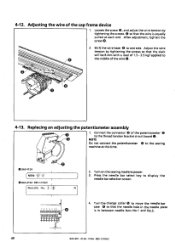
...the wire tension by tightening the screws 6 so that the wire is in the needle plate is equally pulled at this time. 0 Ftt0 • BAS-412A NBN: -,2 • BAS 416A • BES-1210AC Needle No. '1 2. Replacing an adjusting the potentiometer assembly 1. Loosen the screw 6, and adjust the wire tension by tightening ...the screws so that the needle hole in between needle bars No.1 and No.2. 49 BAS-401 • 412A • 416A- 4-12. NOTE Do not connect the potentiometer 6 to the thread tension bracket circuit board 0.
...the wire tension by tightening the screws 6 so that the wire is in the needle plate is equally pulled at this time. 0 Ftt0 • BAS-412A NBN: -,2 • BAS 416A • BES-1210AC Needle No. '1 2. Replacing an adjusting the potentiometer assembly 1. Loosen the screw 6, and adjust the wire tension by tightening ...the screws so that the needle hole in between needle bars No.1 and No.2. 49 BAS-401 • 412A • 416A- 4-12. NOTE Do not connect the potentiometer 6 to the thread tension bracket circuit board 0.

Service Manual
Page 120
... inching after thread trimming Use in the memory.) Even if another floppy disk is done. It may occur errors or hinder correct sewing. • BAS-401 • BAS-416A • BES-1210AC 7-16-2. If the power is inserted during data reading and sewing. DIP switch functions on main printed circuit board NOTE The... is inserted during data reading or sewing of the machine should be stored in conjunction with SW1 To display Japanese To display English 113 BAS-401 412A -416A• BES-1210AC switch number SW1 SW2 SW3 SW4 SWS SW6 SW7 SW8 state OFF ON OFF ON OFF ON OFF ON OFF ON...
... inching after thread trimming Use in the memory.) Even if another floppy disk is done. It may occur errors or hinder correct sewing. • BAS-401 • BAS-416A • BES-1210AC 7-16-2. If the power is inserted during data reading and sewing. DIP switch functions on main printed circuit board NOTE The... is inserted during data reading or sewing of the machine should be stored in conjunction with SW1 To display Japanese To display English 113 BAS-401 412A -416A• BES-1210AC switch number SW1 SW2 SW3 SW4 SWS SW6 SW7 SW8 state OFF ON OFF ON OFF ON OFF ON OFF ON...

Service Manual
Page 140
... the course of "problem determination and solution table." 5. appears in the first column of action to follow 4. indicates turning-off the power switch. 133 BAS-401 • 412A - 416A • BES-1210AC indicates setting-up operation. Symbols r indicates manual operation. 2. indicates switch operation. 3. indicates that the procedure to follow , using a yes-or...
... the course of "problem determination and solution table." 5. appears in the first column of action to follow 4. indicates turning-off the power switch. 133 BAS-401 • 412A - 416A • BES-1210AC indicates setting-up operation. Symbols r indicates manual operation. 2. indicates switch operation. 3. indicates that the procedure to follow , using a yes-or...
Service Manual
Page 152
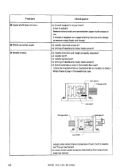
... thread tangled in needle bar flip-up mechanism. • Is rotary hook holder properly attached so that rotary hook does not rotate? 145 BAS-401 • 412A • 416A • BES-1210AC If thread is tangled, turn . ■ Stitch cannot be made. ■ Needle breaks. When there is needle bent? • Is...
... thread tangled in needle bar flip-up mechanism. • Is rotary hook holder properly attached so that rotary hook does not rotate? 145 BAS-401 • 412A • 416A • BES-1210AC If thread is tangled, turn . ■ Stitch cannot be made. ■ Needle breaks. When there is needle bent? • Is...

Service Manual
Page 165
.../il Xifk7f X -PULSE MOTOR Yiik7S - 2 Y -PULSE MOTOR MACHINE MOTOR Q POWER TABLE 70 1 541 FLOPPY UNIT 4 •SITIt247 .7 CAP SWITCH KEYBOARD UNIT BAS-416A Control block diagram BAS-401 • 412A • 416A • BES-1210AC 158 ROTARY ENCODER Ms STOP POSITION SENSOR ikSK 7 L MACHINE HEAD 7 POTENTIONHETEI 0 0,11%1J/ THREAD TRIMMING SOLENOID 0 7-0i - V1.04...
.../il Xifk7f X -PULSE MOTOR Yiik7S - 2 Y -PULSE MOTOR MACHINE MOTOR Q POWER TABLE 70 1 541 FLOPPY UNIT 4 •SITIt247 .7 CAP SWITCH KEYBOARD UNIT BAS-416A Control block diagram BAS-401 • 412A • 416A • BES-1210AC 158 ROTARY ENCODER Ms STOP POSITION SENSOR ikSK 7 L MACHINE HEAD 7 POTENTIONHETEI 0 0,11%1J/ THREAD TRIMMING SOLENOID 0 7-0i - V1.04...


