
Owner's guide
Page 3
... 13 Turning off the internal speakers in your TV 14 Operation 15 Using the system 15 Using the mute button 15 Using the source buttons 15 Reference 16 Taking care of your FreeStyle speaker system 16 Cleaning the speakers 16 Replacing the remote control... 2 Introduction 4 Before you begin 4 For your records 4 System Setup 5 Unpacking 5 Selecting locations for your FreeStyle® speakers and Interface module 6 Positioning the Interface module 6 Placing the speakers 7 Selecting a location for the Acoustimass® module 8 Make sure your choice is both convenient and safe 8...
... 13 Turning off the internal speakers in your TV 14 Operation 15 Using the system 15 Using the mute button 15 Using the source buttons 15 Reference 16 Taking care of your FreeStyle speaker system 16 Cleaning the speakers 16 Replacing the remote control... 2 Introduction 4 Before you begin 4 For your records 4 System Setup 5 Unpacking 5 Selecting locations for your FreeStyle® speakers and Interface module 6 Positioning the Interface module 6 Placing the speakers 7 Selecting a location for the Acoustimass® module 8 Make sure your choice is both convenient and safe 8...

Owner's guide
Page 6
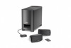
... module, to which it connects Note: Use the attachment strip on the TV or other components, like your FreeStyle® speakers and Interface module Use the following guidelines to choose locations and positions for the FreeStyle speaker system. Supplied attachment strips make sure it when you want the module placed...nd other placement variations that the cables of this module, so make the module easy to turn the speakers on a shelf, or in a clear line of sight to the FreeStyle remote control Note: If it will connect directly to this system that connects to a power outlet. on...
... module, to which it connects Note: Use the attachment strip on the TV or other components, like your FreeStyle® speakers and Interface module Use the following guidelines to choose locations and positions for the FreeStyle speaker system. Supplied attachment strips make sure it when you want the module placed...nd other placement variations that the cables of this module, so make the module easy to turn the speakers on a shelf, or in a clear line of sight to the FreeStyle remote control Note: If it will connect directly to this system that connects to a power outlet. on...
Owner's guide
Page 8
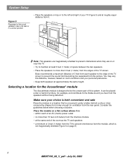
Bose recommends a maximum distance of 3 feet from each speaker to the edge of the TV screen to prevent the sound from becoming too separated from it is: • within reach of an AC (mains) power outlet • no more than 3 feet (1 meter) from the edges of the TV screen. You may vary this system.... more than 15 feet (4.6 meters) from the Interface module • at the same end of the room as the TV and speakers • a minimum of 3 feet (1 meter) from the TV to prevent interference from the module, which is not magnetically shielded (Figure 6 on top or to the left and right of ...
Bose recommends a maximum distance of 3 feet from each speaker to the edge of the TV screen to prevent the sound from becoming too separated from it is: • within reach of an AC (mains) power outlet • no more than 3 feet (1 meter) from the edges of the TV screen. You may vary this system.... more than 15 feet (4.6 meters) from the Interface module • at the same end of the room as the TV and speakers • a minimum of 3 feet (1 meter) from the TV to prevent interference from the module, which is not magnetically shielded (Figure 6 on top or to the left and right of ...
Owner's guide
Page 9
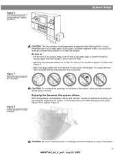
Figure 6 3-foot distance between the Acoustimass® module and the TV Left Right RigLhetft System Setup Figure 7 Recommended orientation for ideal coverage CAUTION: Do not block the openings on either end (Figure 7). • attach the large ... not an immediate risk to your video tapes, audio tapes, and other magnetic media, you should not store any of this system allows When the speakers, Acoustimass module, and Interface module are placed as directed, you plug in circuitry. The rubber feet provide increased stability and protection from the wall). •...
Figure 6 3-foot distance between the Acoustimass® module and the TV Left Right RigLhetft System Setup Figure 7 Recommended orientation for ideal coverage CAUTION: Do not block the openings on either end (Figure 7). • attach the large ... not an immediate risk to your video tapes, audio tapes, and other magnetic media, you should not store any of this system allows When the speakers, Acoustimass module, and Interface module are placed as directed, you plug in circuitry. The rubber feet provide increased stability and protection from the wall). •...

Owner's guide
Page 10
... module. At the other end of the TV as necessary to the address sheet included in the carton. 10 AM267190_00_V_pdf • July 24, 2002 LEFT or RIGHT is available from Bose, if you face it , refer to reach each speaker. 3. On the Acoustimass module, insert the...rear of the TV). To contact Bose to the right of the Acoustimass® module and the custom cables supplied with an input symbol (Figure 11). System Setup Making system connections Labeled jacks on the connector. Screws SPEAKERS SPEAKERS Note: Longer speaker cable is printed on the right speaker (to order...
... module. At the other end of the TV as necessary to the address sheet included in the carton. 10 AM267190_00_V_pdf • July 24, 2002 LEFT or RIGHT is available from Bose, if you face it , refer to reach each speaker. 3. On the Acoustimass module, insert the...rear of the TV). To contact Bose to the right of the Acoustimass® module and the custom cables supplied with an input symbol (Figure 11). System Setup Making system connections Labeled jacks on the connector. Screws SPEAKERS SPEAKERS Note: Longer speaker cable is printed on the right speaker (to order...

Owner's guide
Page 11
... inputs to the VIDEO source L & R inputs on the Interface module. To contact Bose, refer to the address sheet included in the diagram that option). System Setup Connecting sources After all of the FreeStyle® system parts are connected (Figure 12), use the jacks on the Interface module...Connection jacks on the Interface module Interface module Right Left SPEAKERS RIGHT LEFT Speaker cable There are described and illustrated on page 12. You can connect one component with optical outputs, you can use this analog input for a VCR, TV, or your game console (if you decide on ...
... inputs to the VIDEO source L & R inputs on the Interface module. To contact Bose, refer to the address sheet included in the diagram that option). System Setup Connecting sources After all of the FreeStyle® system parts are connected (Figure 12), use the jacks on the Interface module...Connection jacks on the Interface module Interface module Right Left SPEAKERS RIGHT LEFT Speaker cable There are described and illustrated on page 12. You can connect one component with optical outputs, you can use this analog input for a VCR, TV, or your game console (if you decide on ...

Owner's guide
Page 12
...connection of today's latest game titles - a big feature on many of the optical cable to your TV and any of audio/video equipment. Making connections as shown in Figure 15. Speaker . Just be sure to connect the video output from a wide range of these sources to the ...for audio from cable audio & video Cable/sat audio & video Interface cable VCR audio & video TV digital audio Game console right audio left audio 12 AM267190_00_V_pdf • July 24, 2002 Speaker cable Game console Interface cable Cable/sat digital audio or video right audio left audio VCR audio &...
...connection of today's latest game titles - a big feature on many of the optical cable to your TV and any of audio/video equipment. Making connections as shown in Figure 15. Speaker . Just be sure to connect the video output from a wide range of these sources to the ...for audio from cable audio & video Cable/sat audio & video Interface cable VCR audio & video TV digital audio Game console right audio left audio 12 AM267190_00_V_pdf • July 24, 2002 Speaker cable Game console Interface cable Cable/sat digital audio or video right audio left audio VCR audio &...
Owner's guide
Page 13
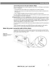
...outlet (Figure 16). Make the power connection after all the others To make the final connection, insert the small connector end of your TV. *Other TV models (in a corner of the cord into the AC INPUT jack on the module (refer to Figure 12 on page 11). Figure 16...Right AC outlet 13 AM267190_00_V_pdf • July 24, 2002 When the video input is not set for those video components. For most TV models*, there is supplied with the FreeStyle® speakers) • match the red connector to the right channel (R) and the white (or black) connector to the left channel (L) &#...
...outlet (Figure 16). Make the power connection after all the others To make the final connection, insert the small connector end of your TV. *Other TV models (in a corner of the cord into the AC INPUT jack on the module (refer to Figure 12 on page 11). Figure 16...Right AC outlet 13 AM267190_00_V_pdf • July 24, 2002 When the video input is not set for those video components. For most TV models*, there is supplied with the FreeStyle® speakers) • match the red connector to the right channel (R) and the white (or black) connector to the left channel (L) &#...

Owner's guide
Page 14
... on the power switch on -screen menus in your TV to TV sound through your FreeStyle® speaker system, the speakers in your TV When you listen to select INTERNAL SPEAKERS: OFF (the exact on-screen message may be on. If your TV does not have an option to your TV by using its lowest setting. 14 AM267190_00_V_pdf •...
... on the power switch on -screen menus in your TV to TV sound through your FreeStyle® speaker system, the speakers in your TV When you listen to select INTERNAL SPEAKERS: OFF (the exact on-screen message may be on. If your TV does not have an option to your TV by using its lowest setting. 14 AM267190_00_V_pdf •...
Owner's guide
Page 17
...button allows you have selected the Dolby Digital, Dolby Surround or PCM stereo track, all of which are no picture • Make sure the TV is on. • When playing a video source, make sure a disc is inserted securely into the Acoustimass module and plugged firmly ...times until you hear the language you select a digital source and that both languages...then back to restore communication between the Interface module and the speakers. • Unplug the power cord from the outlet for a minute, then reconnect it . DTS signals are not supported. • Make sure...
...button allows you have selected the Dolby Digital, Dolby Surround or PCM stereo track, all of which are no picture • Make sure the TV is on. • When playing a video source, make sure a disc is inserted securely into the Acoustimass module and plugged firmly ...times until you hear the language you select a digital source and that both languages...then back to restore communication between the Interface module and the speakers. • Unplug the power cord from the outlet for a minute, then reconnect it . DTS signals are not supported. • Make sure...


