Owner's guide
Page 8
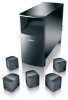
...into the connectors. Setting Up Connecting the speakers CAUTION: Never connect the cube speakers directly to the Acoustimass module (Figure 5). Front speaker cables have two wires. The red collars on the + wire are not intended for in electrical shock or damage to the receiver. Always connect them to the ...powered Acoustimass® module, then connect the module to your system. The other ends of the ...
...into the connectors. Setting Up Connecting the speakers CAUTION: Never connect the cube speakers directly to the Acoustimass module (Figure 5). Front speaker cables have two wires. The red collars on the + wire are not intended for in electrical shock or damage to the receiver. Always connect them to the ...powered Acoustimass® module, then connect the module to your system. The other ends of the ...
Owner's guide
Page 9
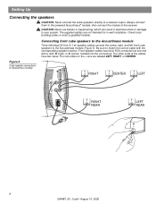
... 3. Rear speaker cables have two wires. The red collars on the Acoustimass® module. Connect the wire pair marked LEFT REAR to secure the wires. 2. Press the terminal tab on the Acoustimass module. 9 264887_00 _V.pdf • August 13, 2002 Connect the wire pair marked RIGHT to the right ... it). 3. Plug the other ends of the cube speaker. Connect the wire pair marked RIGHT REAR to the Acoustimass module with LR (left front cube speaker. 4. Connecting rear cube speakers to the Acoustimass module Each rear cube speaker is connected to the right rear cube speaker ...
... 3. Rear speaker cables have two wires. The red collars on the Acoustimass® module. Connect the wire pair marked LEFT REAR to secure the wires. 2. Press the terminal tab on the Acoustimass module. 9 264887_00 _V.pdf • August 13, 2002 Connect the wire pair marked RIGHT to the right ... it). 3. Plug the other ends of the cube speaker. Connect the wire pair marked RIGHT REAR to the Acoustimass module with LR (left front cube speaker. 4. Connecting rear cube speakers to the Acoustimass module Each rear cube speaker is connected to the right rear cube speaker ...
Owner's guide
Page 10
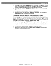
...If applicable, connect the RCA plug on the system input cable to the LFE/SUBWOOFER OUT jack on the Acoustimass module. The wire pairs of the connections (+ to + and - Each wire pair is marked on the other ; terminal. Tighten the two thumbscrews to your receiver. 10 264887_00 _V...your surround receiver. Setting Up Connecting the Acoustimass® module to the receiver The 20-foot (6.1 m) system input cable connects the module to your system. to -). • Attach each marked wire (+) to the appropriate + terminal. • Attach each wire connects to the receiver. Insert the ...
...If applicable, connect the RCA plug on the system input cable to the LFE/SUBWOOFER OUT jack on the Acoustimass module. The wire pairs of the connections (+ to + and - Each wire pair is marked on the other ; terminal. Tighten the two thumbscrews to your receiver. 10 264887_00 _V...your surround receiver. Setting Up Connecting the Acoustimass® module to the receiver The 20-foot (6.1 m) system input cable connects the module to your system. to -). • Attach each marked wire (+) to the appropriate + terminal. • Attach each wire connects to the receiver. Insert the ...
Owner's guide
Page 12
...receiver. 12 264887_00 _V.pdf • August 13, 2002 Check that the wires are connected to the proper terminals according to the cube speakers (Figure 5 and Figure 6). to + and - Your Acoustimass speaker system will turn it on and off automatically as it receives a ... variations and spikes can eliminate the vast majority of the powered Acoustimass module into an AC (mains) receptacle. A quality suppressor can damage electronic components in your room. Connecting the Acoustimass module to power Note: Bose® recommends using a quality surge suppressor on all system connections...
...receiver. 12 264887_00 _V.pdf • August 13, 2002 Check that the wires are connected to the proper terminals according to the cube speakers (Figure 5 and Figure 6). to + and - Your Acoustimass speaker system will turn it on and off automatically as it receives a ... variations and spikes can eliminate the vast majority of the powered Acoustimass module into an AC (mains) receptacle. A quality suppressor can damage electronic components in your room. Connecting the Acoustimass module to power Note: Bose® recommends using a quality surge suppressor on all system connections...
Owner's guide
Page 15
...DVD, laser disc, or broadcast programming) is Dolby Digital encoded. To contact Bose directly, refer to the list of service of external components connected to the receiver. Sound is distorted • Make sure speaker wire is not damaged. • Reduce the volume of fices and phone ... your sound source and try the following solutions. Move it farther away from cube speakers • Be sure the powered Acoustimass module is plugged in solving problems, contact Bose customer service. If you still have a problem with the digital input on . • Be sure to select a source...
...DVD, laser disc, or broadcast programming) is Dolby Digital encoded. To contact Bose directly, refer to the list of service of external components connected to the receiver. Sound is distorted • Make sure speaker wire is not damaged. • Reduce the volume of fices and phone ... your sound source and try the following solutions. Move it farther away from cube speakers • Be sure the powered Acoustimass module is plugged in solving problems, contact Bose customer service. If you still have a problem with the digital input on . • Be sure to select a source...
Owner's guide
Page 17
... (black), UB-20W (white) • Module input cable adapter for use with existing wiring: PN 267138-001 (black) PN 267138-002 (white) • Module-to Bose®. Please fill out the information section on the warranty card that came with ...existing wiring: PN 267139-001 (black) PN 267139-002 (white) • Module 20 ft (6.1 m) input extension cable: PN198221-001 (black) PN198221-002 (white) 17 264887_00 _V.pdf • August 13, 2002 Reference Warranty period Your Acoustimass...
... (black), UB-20W (white) • Module input cable adapter for use with existing wiring: PN 267138-001 (black) PN 267138-002 (white) • Module-to Bose®. Please fill out the information section on the warranty card that came with ...existing wiring: PN 267139-001 (black) PN 267139-002 (white) • Module 20 ft (6.1 m) input extension cable: PN198221-001 (black) PN198221-002 (white) 17 264887_00 _V.pdf • August 13, 2002 Reference Warranty period Your Acoustimass...


