
Owner's guide
Page 1
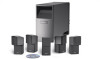
The Bose® Acoustimass® 6 Series III and Acoustimass 10 Series III Home Theater Speaker Systems Owner's Guide August 13 , 2002 AM264887_00_V.pdf Bose Corporation
The Bose® Acoustimass® 6 Series III and Acoustimass 10 Series III Home Theater Speaker Systems Owner's Guide August 13 , 2002 AM264887_00_V.pdf Bose Corporation
Owner's guide
Page 2
...Dolby" and the double-D symbol are trademarks of electric shock. Additional safety information See the additional safety information on the Acoustimass module: The lightning flash with arrowhead symbol, within the system enclosure that may be located on the Important Safety... Instructions page enclosed with this owner's guide. ©2002 Bose Corporation. CAUTION: No naked flame sources, such as marked on the apparatus. Please save your speaker system. Manufactured under license from Dolby Laboratories. REFER SERVICING TO QUALIFIED PERSONNEL. ...
...Dolby" and the double-D symbol are trademarks of electric shock. Additional safety information See the additional safety information on the Acoustimass module: The lightning flash with arrowhead symbol, within the system enclosure that may be located on the Important Safety... Instructions page enclosed with this owner's guide. ©2002 Bose Corporation. CAUTION: No naked flame sources, such as marked on the apparatus. Please save your speaker system. Manufactured under license from Dolby Laboratories. REFER SERVICING TO QUALIFIED PERSONNEL. ...
Owner's guide
Page 3
... realistic home theater sound 5 Front center cube speaker 6 Front left and right cube speakers 7 Rear cube speakers 7 Powered Acoustimass® module 7 Connecting the speakers 8 Connecting front cube speakers to the Acoustimass module 8 Connecting rear cube speakers to the Acoustimass module 9 Connecting the Acoustimass module to the receiver 10 Checking the connections 12 Connecting the Acoustimass module to power 12 Using your system...
... realistic home theater sound 5 Front center cube speaker 6 Front left and right cube speakers 7 Rear cube speakers 7 Powered Acoustimass® module 7 Connecting the speakers 8 Connecting front cube speakers to the Acoustimass module 8 Connecting rear cube speakers to the Acoustimass module 9 Connecting the Acoustimass module to the receiver 10 Checking the connections 12 Connecting the Acoustimass module to power 12 Using your system...
Owner's guide
Page 4
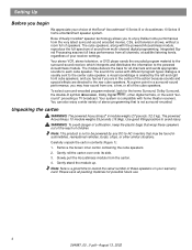
..., ships, or other digital formats, or the word "sur- Note: This product is not to -AC inverters that wrap these speakers on your choice of the Bose® Acoustimass® 6 Series III or Acoustimass 10 Series III home entertainment speaker system. Gently roll the carton over onto its side. 3. Note: Now is not surround-encoded. Setting Up Before you to...
..., ships, or other digital formats, or the word "sur- Note: This product is not to -AC inverters that wrap these speakers on your choice of the Bose® Acoustimass® 6 Series III or Acoustimass 10 Series III home entertainment speaker system. Gently roll the carton over onto its side. 3. Note: Now is not surround-encoded. Setting Up Before you to...
Owner's guide
Page 5
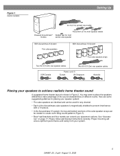
... room-filling sound patterns (Figure 3). • Bose® wall brackets and floor stands can be used for front center cube speaker With Acoustimass 6 System Five cube speakers With Acoustimass 10 System Five cube speaker arrays Two 50-ft (15.2m) rear speaker cables Two 50-ft (15.2m) rear speaker cables USA/Canada Power cord (1) Europe UK...
... room-filling sound patterns (Figure 3). • Bose® wall brackets and floor stands can be used for front center cube speaker With Acoustimass 6 System Five cube speakers With Acoustimass 10 System Five cube speaker arrays Two 50-ft (15.2m) rear speaker cables Two 50-ft (15.2m) rear speaker cables USA/Canada Power cord (1) Europe UK...
Owner's guide
Page 6
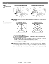
... of charge, by contacting Bose® Customer Service. Sound should seem to come from your television. Vibration can cause them to move, particularly on top of your cube speakers. See the list of phone numbers included with your screen. For Acoustimass 6 Series III For Acoustimass 10 Series III Front center cube speaker The front center cube speaker localizes action and dialogue...
... of charge, by contacting Bose® Customer Service. Sound should seem to come from your television. Vibration can cause them to move, particularly on top of your cube speakers. See the list of phone numbers included with your screen. For Acoustimass 6 Series III For Acoustimass 10 Series III Front center cube speaker The front center cube speaker localizes action and dialogue...
Owner's guide
Page 7
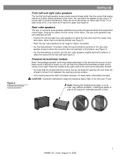
... than from directly behind (see Figure 3). • Place the rear cube speakers at ear height or higher, if possible. • For the Acoustimass® 10 system, rotate the top and bottom sections of the rear cube speaker arrays to direct the sound to the front and back of your TV, ...may reduce ventilation, inhibiting its ability to play at the same end of time. 7 264887_00 _V.pdf • August 13, 2002 Powered Acoustimass module Bose® Acoustimass speaker technology takes advantage of the fact that expand the visual image, bringing the viewer into the center of sight. Rear cube...
... than from directly behind (see Figure 3). • Place the rear cube speakers at ear height or higher, if possible. • For the Acoustimass® 10 system, rotate the top and bottom sections of the rear cube speaker arrays to direct the sound to the front and back of your TV, ...may reduce ventilation, inhibiting its ability to play at the same end of time. 7 264887_00 _V.pdf • August 13, 2002 Powered Acoustimass module Bose® Acoustimass speaker technology takes advantage of the fact that expand the visual image, bringing the viewer into the center of sight. Rear cube...
Owner's guide
Page 8
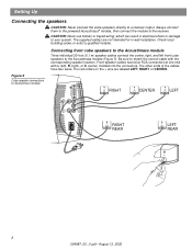
... which can result in -wall installation. Be sure to match the correct cable with L (left front cube speakers to your system. Figure 5 Cube speaker connections to the Acoustimass module Three individual 20-foot (6.1 m) speaker cables connect the center, right, and left ), R (right), or C (center) molded into the connectors.... Connecting front cube speakers to Acoustimass module RIGHT CENTER LEFT Audio Input Left Center Right Front Front Front Right Rear Audio Output Left Rear RIGHT REAR LEFT ...
... which can result in -wall installation. Be sure to match the correct cable with L (left front cube speakers to your system. Figure 5 Cube speaker connections to the Acoustimass module Three individual 20-foot (6.1 m) speaker cables connect the center, right, and left ), R (right), or C (center) molded into the connectors.... Connecting front cube speakers to Acoustimass module RIGHT CENTER LEFT Audio Input Left Center Right Front Front Front Right Rear Audio Output Left Rear RIGHT REAR LEFT ...
Owner's guide
Page 9
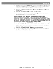
...to the left rear) and RR (right rear) molded into the connectors. Connecting rear cube speakers to the Acoustimass module Each rear cube speaker is connected to secure the wires. 2. The red collars on the Acoustimass module. 9 264887_00 _V.pdf • August 13, 2002 Press the terminal tab on ...the Acoustimass® module. Release the tab to the Acoustimass module with a 50-foot (15 m) speaker cable (Figure 5). Release the tab to match the correct cable with LR (left front cube speaker. 4. Plug the other end of each cable into the...
...to the left rear) and RR (right rear) molded into the connectors. Connecting rear cube speakers to the Acoustimass module Each rear cube speaker is connected to secure the wires. 2. The red collars on the Acoustimass module. 9 264887_00 _V.pdf • August 13, 2002 Press the terminal tab on ...the Acoustimass® module. Release the tab to the Acoustimass module with a 50-foot (15 m) speaker cable (Figure 5). Release the tab to match the correct cable with LR (left front cube speaker. 4. Plug the other end of each cable into the...
Owner's guide
Page 11
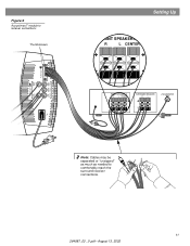
Figure 6 Acoustimass® module to receiver connections Thumbscrews Audio Output Left Rear Right Rear Audio Input Left Center Right Front Front Front Setting Up FRONT SPEAKERS A R L CENTER FRONT SPEAKERS A R L CENTER SURROUND SPEAKERS R L LFE/SUBWOOFER OUT Note: Cables may be separated or "unzipped" as much as needed to comfortably reach the surround receiver connections. 11 264887_00 _V.pdf • August 13, 2002
Figure 6 Acoustimass® module to receiver connections Thumbscrews Audio Output Left Rear Right Rear Audio Input Left Center Right Front Front Front Setting Up FRONT SPEAKERS A R L CENTER FRONT SPEAKERS A R L CENTER SURROUND SPEAKERS R L LFE/SUBWOOFER OUT Note: Cables may be separated or "unzipped" as much as needed to comfortably reach the surround receiver connections. 11 264887_00 _V.pdf • August 13, 2002
Owner's guide
Page 12
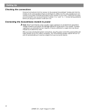
... before you have checked all system connections, plug the power cord of failures attributed to your surround receiver in your room. Your Acoustimass speaker system will turn it receives a signal from the module to + and - Check that the wires are connected to the proper terminals...on and off automatically as it on all connections from the receiver to the powered Acoustimass® module and from your receiver in any system. Connecting the Acoustimass module to -). to power Note: Bose® recommends using a quality surge suppressor on . Setting Up Checking the connections...
... before you have checked all system connections, plug the power cord of failures attributed to your surround receiver in your room. Your Acoustimass speaker system will turn it receives a signal from the module to + and - Check that the wires are connected to the proper terminals...on and off automatically as it on all connections from the receiver to the powered Acoustimass® module and from your receiver in any system. Connecting the Acoustimass module to -). to power Note: Bose® recommends using a quality surge suppressor on . Setting Up Checking the connections...
Owner's guide
Page 13
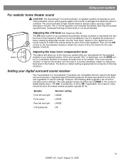
Using your system For realistic home theater sound CAUTION: The Acoustimass® 6 and Acoustimass 10 speaker systems incorporate an automatic protection circuit, which guards against most kinds of listening situations. Sustained listening at high volume levels to ... regardless of the module. Adjusting the LFE level (low frequency effects) The LFE level control on your digital surround sound receiver Your Acoustimass 6 or Acoustimass 10 speakers are compatible with the output from electrical stress or overload. The LFE, or subwoofer, is appropriate for each of these levels is ...
Using your system For realistic home theater sound CAUTION: The Acoustimass® 6 and Acoustimass 10 speaker systems incorporate an automatic protection circuit, which guards against most kinds of listening situations. Sustained listening at high volume levels to ... regardless of the module. Adjusting the LFE level (low frequency effects) The LFE level control on your digital surround sound receiver Your Acoustimass 6 or Acoustimass 10 speakers are compatible with the output from electrical stress or overload. The LFE, or subwoofer, is appropriate for each of these levels is ...
Owner's guide
Page 14
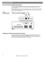
DIGITAL PLAY IN IN (OPTICAL) PLAY IN (COAXIAL) DIGITAL PLAY IN IN (OPTICAL) PLAY IN (COAXIAL) FRONT SPEAKERS R L SURROUND SPEAKERS R REAR L CENTER Setting your analog surround sound receiver For analog surround sound (not digital) applications, we recommend that came with your surround ... receiver (Figure 7). Before you set the surround-sound center mode of your receiver to select the digital ouput in the setup menu of each speaker. 14 264887_00 _V.pdf • August 13, 2002 Follow your surround receiver. Using your system Be sure to get the digital audio signal...
DIGITAL PLAY IN IN (OPTICAL) PLAY IN (COAXIAL) DIGITAL PLAY IN IN (OPTICAL) PLAY IN (COAXIAL) FRONT SPEAKERS R L SURROUND SPEAKERS R REAR L CENTER Setting your analog surround sound receiver For analog surround sound (not digital) applications, we recommend that came with your surround ... receiver (Figure 7). Before you set the surround-sound center mode of your receiver to select the digital ouput in the setup menu of each speaker. 14 264887_00 _V.pdf • August 13, 2002 Follow your surround receiver. Using your system Be sure to get the digital audio signal...
Owner's guide
Page 15
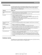
... digital programming, verify that the receiver is not damaged. • Reduce the volume of the DVD player with your Acoustimass® speaker system, turn off your receiver and player for service. To contact Bose directly, refer to the list of service of fices and phone numbers enclosed in . • For digital sound...
... digital programming, verify that the receiver is not damaged. • Reduce the volume of the DVD player with your Acoustimass® speaker system, turn off your receiver and player for service. To contact Bose directly, refer to the list of service of fices and phone numbers enclosed in . • For digital sound...
Owner's guide
Page 16
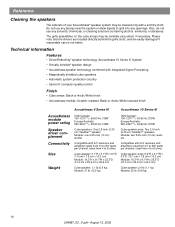
... circuitry • Syncom® computer quality control Finish • Cube arrays: Black or Arctic White finish • Acoustimass module: Scratch-resistant Black or Arctic White textured finish Acoustimass 6 Series III Acoustimass 10 Series III Acoustimass module power rating Speaker driver complement Connectivity Size Weight USA/Canada: 100-127V 50/60 Hz 135W Europe/Australia: 220-240V 50/60...
... circuitry • Syncom® computer quality control Finish • Cube arrays: Black or Arctic White finish • Acoustimass module: Scratch-resistant Black or Arctic White textured finish Acoustimass 6 Series III Acoustimass 10 Series III Acoustimass module power rating Speaker driver complement Connectivity Size Weight USA/Canada: 100-127V 50/60 Hz 135W Europe/Australia: 220-240V 50/60...
Owner's guide
Page 17
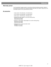
... on the card and mail it to -cube speaker cable adapter for use with your system. Please fill out the information section on the warranty card that came with existing wiring: PN 267138-001 (black) PN 267138-002 (white) • Module-to Bose®. Accessories • Table stands: UTS-20B (black...) • Module 20 ft (6.1 m) input extension cable: PN198221-001 (black) PN198221-002 (white) 17 264887_00 _V.pdf • August 13, 2002 Reference Warranty period Your Acoustimass® speaker system is covered by a limited transferable warranty.
... on the card and mail it to -cube speaker cable adapter for use with your system. Please fill out the information section on the warranty card that came with existing wiring: PN 267138-001 (black) PN 267138-002 (white) • Module-to Bose®. Accessories • Table stands: UTS-20B (black...) • Module 20 ft (6.1 m) input extension cable: PN198221-001 (black) PN198221-002 (white) 17 264887_00 _V.pdf • August 13, 2002 Reference Warranty period Your Acoustimass® speaker system is covered by a limited transferable warranty.

