Owner's guide
Page 5
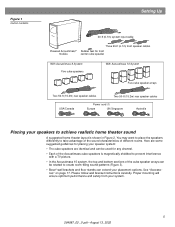
... • Bose® wall brackets and floor stands can extend your placement options. See "Accessories" on page 17. Figure 1 Carton contents Setting Up 20-ft (6.1m) system input cable Powered Acoustimass® module Three 20-ft (6.1m) front speaker cables Rubber feet for...the Acoustimass 10 system, the top and bottom sections of the cube speaker arrays can be used for front center cube speaker With Acoustimass 6 System Five cube speakers With Acoustimass 10 System Five cube speaker arrays Two 50-ft (15.2m) rear speaker cables Two 50-ft (15.2m) rear speaker cables USA/...
... • Bose® wall brackets and floor stands can extend your placement options. See "Accessories" on page 17. Figure 1 Carton contents Setting Up 20-ft (6.1m) system input cable Powered Acoustimass® module Three 20-ft (6.1m) front speaker cables Rubber feet for...the Acoustimass 10 system, the top and bottom sections of the cube speaker arrays can be used for front center cube speaker With Acoustimass 6 System Five cube speakers With Acoustimass 10 System Five cube speaker arrays Two 50-ft (15.2m) rear speaker cables Two 50-ft (15.2m) rear speaker cables USA/...
Owner's guide
Page 8
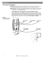
... labeled LEFT, RIGHT, or CENTER. Be sure to the receiver. The other ends of the cables have blue RCA connectors at one end with the corresponding speaker location. Connecting front cube speakers to the Acoustimass module Three individual 20-foot (6.1 m) speaker cables connect the center, right, and left ), R (right), or C (center) molded into the connectors. Figure...
... labeled LEFT, RIGHT, or CENTER. Be sure to the receiver. The other ends of the cables have blue RCA connectors at one end with the corresponding speaker location. Connecting front cube speakers to the Acoustimass module Three individual 20-foot (6.1 m) speaker cables connect the center, right, and left ), R (right), or C (center) molded into the connectors. Figure...
Owner's guide
Page 9
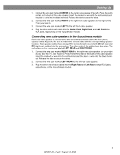
...The red collars on the back of the TV as you face it). 3. Connect the wire pair marked CENTER to the Acoustimass module with a 50-foot (15 m) speaker cable (Figure 5). Insert the marked (+) wire into the red terminal and the plain (-) wire into the black terminal. Connect the...2. See Figure 5. Plug the other end of the cables have orange RCA connectors at one end with the corresponding speaker location. The other ends of each cable into the connectors. Release the tab to the right rear cube speaker (on the Acoustimass module. 9 264887_00 _V.pdf • August 13,...
...The red collars on the back of the TV as you face it). 3. Connect the wire pair marked CENTER to the Acoustimass module with a 50-foot (15 m) speaker cable (Figure 5). Insert the marked (+) wire into the red terminal and the plain (-) wire into the black terminal. Connect the...2. See Figure 5. Plug the other end of the cables have orange RCA connectors at one end with the corresponding speaker location. The other ends of each cable into the connectors. Release the tab to the right rear cube speaker (on the Acoustimass module. 9 264887_00 _V.pdf • August 13,...
Owner's guide
Page 11
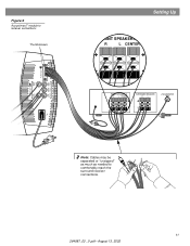
Figure 6 Acoustimass® module to receiver connections Thumbscrews Audio Output Left Rear Right Rear Audio Input Left Center Right Front Front Front Setting Up FRONT SPEAKERS A R L CENTER FRONT SPEAKERS A R L CENTER SURROUND SPEAKERS R L LFE/SUBWOOFER OUT Note: Cables may be separated or "unzipped" as much as needed to comfortably reach the surround receiver connections. 11 264887_00 _V.pdf • August 13, 2002
Figure 6 Acoustimass® module to receiver connections Thumbscrews Audio Output Left Rear Right Rear Audio Input Left Center Right Front Front Front Setting Up FRONT SPEAKERS A R L CENTER FRONT SPEAKERS A R L CENTER SURROUND SPEAKERS R L LFE/SUBWOOFER OUT Note: Cables may be separated or "unzipped" as much as needed to comfortably reach the surround receiver connections. 11 264887_00 _V.pdf • August 13, 2002
Owner's guide
Page 15
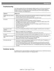
... with the digital input on your receiver is processing a signal from cube speakers • Be sure the powered Acoustimass module is plugged in and the receiver is correct. If you have a problem, contact your Bose® dealer to arrange for DVD sound. • Disconnect any headphones....audio source selected is turned on. No sound • Check the speaker connections. • Make sure that the powered Acoustimass module is plugged in. • For digital sound, be sure a coaxial or optical cable connects the digital output of fices and phone numbers enclosed in ...
... with the digital input on your receiver is processing a signal from cube speakers • Be sure the powered Acoustimass module is plugged in and the receiver is correct. If you have a problem, contact your Bose® dealer to arrange for DVD sound. • Disconnect any headphones....audio source selected is turned on. No sound • Check the speaker connections. • Make sure that the powered Acoustimass module is plugged in. • For digital sound, be sure a coaxial or optical cable connects the digital output of fices and phone numbers enclosed in ...
Owner's guide
Page 17
... _V.pdf • August 13, 2002 Details of the warranty are provided on the card and mail it to -cube speaker cable adapter for use with your system. Reference Warranty period Your Acoustimass® speaker system is covered by a limited transferable warranty. Accessories • Table stands: UTS-20B (black), UTS-20W (white)... • Floor stands: UFS-20B (black), UFS-20W (white) • Wall brackets: UB-20B (black), UB-20W (white) • Module input cable adapter for use with existing wiring: PN 267138-001 (black) PN 267138-002 (white) • Module-to Bose®.
... _V.pdf • August 13, 2002 Details of the warranty are provided on the card and mail it to -cube speaker cable adapter for use with your system. Reference Warranty period Your Acoustimass® speaker system is covered by a limited transferable warranty. Accessories • Table stands: UTS-20B (black), UTS-20W (white)... • Floor stands: UFS-20B (black), UFS-20W (white) • Wall brackets: UB-20B (black), UB-20W (white) • Module input cable adapter for use with existing wiring: PN 267138-001 (black) PN 267138-002 (white) • Module-to Bose®.

