
Owner's guide
Page 1
The Bose® Acoustimass® 6 Series III and Acoustimass 10 Series III Home Theater Speaker Systems Owner's Guide August 13 , 2002 AM264887_00_V.pdf Bose Corporation
The Bose® Acoustimass® 6 Series III and Acoustimass 10 Series III Home Theater Speaker Systems Owner's Guide August 13 , 2002 AM264887_00_V.pdf Bose Corporation
Owner's guide
Page 2
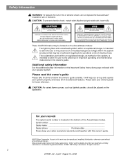
... arrière). These CAUTION marks may be located on the bottom of the Acoustimass module. Please read this work may be of sufficient magnitude to follow this owner's guide. ©2002 Bose Corporation. For your owner's guide for future reference. Manufactured under license from Dolby ... and warranty card together with your system properly, and enjoy all of its advanced features. It will help you set up and operate your speaker system. LA MAINTENANCE DOIT ÊTRE RÉALISÉE PAR UN PERSONNEL QUALIFIÉ. CAUTION: No naked flame sources, such ...
... arrière). These CAUTION marks may be located on the bottom of the Acoustimass module. Please read this work may be of sufficient magnitude to follow this owner's guide. ©2002 Bose Corporation. For your owner's guide for future reference. Manufactured under license from Dolby ... and warranty card together with your system properly, and enjoy all of its advanced features. It will help you set up and operate your speaker system. LA MAINTENANCE DOIT ÊTRE RÉALISÉE PAR UN PERSONNEL QUALIFIÉ. CAUTION: No naked flame sources, such ...
Owner's guide
Page 3
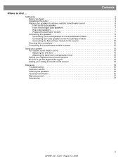
... realistic home theater sound 5 Front center cube speaker 6 Front left and right cube speakers 7 Rear cube speakers 7 Powered Acoustimass® module 7 Connecting the speakers 8 Connecting front cube speakers to the Acoustimass module 8 Connecting rear cube speakers to the Acoustimass module 9 Connecting the Acoustimass module to the receiver 10 Checking the connections 12 Connecting the Acoustimass module to power 12 Using your system...
... realistic home theater sound 5 Front center cube speaker 6 Front left and right cube speakers 7 Rear cube speakers 7 Powered Acoustimass® module 7 Connecting the speakers 8 Connecting front cube speakers to the Acoustimass module 8 Connecting rear cube speakers to the Acoustimass module 9 Connecting the Acoustimass module to the receiver 10 Checking the connections 12 Connecting the Acoustimass module to power 12 Using your system...
Owner's guide
Page 4
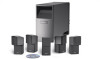
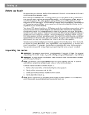
..., or other digital formats, or the word "sur- Bose Virtually Invisible® speaker technology allows you may be powered by the left and right front cube speakers, and you feel as if you begin We appreciate your choice of the Bose® Acoustimass® 6 Series III or Acoustimass 10 Series III home entertainment speaker system. Gently stand the module up. Carefully unpack...
..., or other digital formats, or the word "sur- Bose Virtually Invisible® speaker technology allows you may be powered by the left and right front cube speakers, and you feel as if you begin We appreciate your choice of the Bose® Acoustimass® 6 Series III or Acoustimass 10 Series III home entertainment speaker system. Gently stand the module up. Carefully unpack...
Owner's guide
Page 5
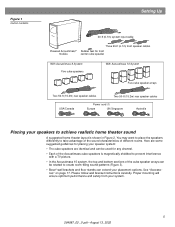
... room-filling sound patterns (Figure 3). • Bose® wall brackets and floor stands can be used for front center cube speaker With Acoustimass 6 System Five cube speakers With Acoustimass 10 System Five cube speaker arrays Two 50-ft (15.2m) rear speaker cables Two 50-ft (15.2m) rear speaker cables USA/Canada Power cord (1) Europe UK...
... room-filling sound patterns (Figure 3). • Bose® wall brackets and floor stands can be used for front center cube speaker With Acoustimass 6 System Five cube speakers With Acoustimass 10 System Five cube speaker arrays Two 50-ft (15.2m) rear speaker cables Two 50-ft (15.2m) rear speaker cables USA/Canada Power cord (1) Europe UK...
Owner's guide
Page 6
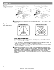
... charge, by contacting Bose® Customer Service. Sound should seem to move, particularly on your system. 6 264887_00 _V.pdf • August 13, 2002 You may obtain additional rubber feet (part number 178321-04), free of four rubber feet provided. For Acoustimass 6 Series III For Acoustimass 10 Series III Front center cube speaker The front center cube speaker localizes action and...
... charge, by contacting Bose® Customer Service. Sound should seem to move, particularly on your system. 6 264887_00 _V.pdf • August 13, 2002 You may obtain additional rubber feet (part number 178321-04), free of four rubber feet provided. For Acoustimass 6 Series III For Acoustimass 10 Series III Front center cube speaker The front center cube speaker localizes action and...
Owner's guide
Page 7
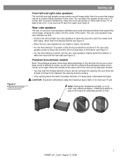
... on its side, may reduce ventilation, inhibiting its ability to locate, so you can place the speaker arrays near a TV screen with no picture interference. Powered Acoustimass module Bose® Acoustimass speaker technology takes advantage of the fact that the source of pure bass sound is difficult to... image wider than from your TV, at ear height or higher, if possible. • For the Acoustimass® 10 system, rotate the top and bottom sections of the rear cube speaker arrays to direct the sound to viewers sitting anywhere in the room. CAUTION: To prevent interference, keep ...
... on its side, may reduce ventilation, inhibiting its ability to locate, so you can place the speaker arrays near a TV screen with no picture interference. Powered Acoustimass module Bose® Acoustimass speaker technology takes advantage of the fact that the source of pure bass sound is difficult to... image wider than from your TV, at ear height or higher, if possible. • For the Acoustimass® 10 system, rotate the top and bottom sections of the rear cube speaker arrays to direct the sound to viewers sitting anywhere in the room. CAUTION: To prevent interference, keep ...
Owner's guide
Page 8
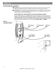
...wire are not intended for in electrical shock or damage to the Acoustimass module (Figure 5). Setting Up Connecting the speakers CAUTION: Never connect the cube speakers directly to Acoustimass module RIGHT CENTER LEFT Audio Input Left Center Right Front Front Front ...RCA connectors at one end with the corresponding speaker location. Figure 5 Cube speaker connections to a receiver output. Always connect them to the powered Acoustimass® module, then connect the module to the Acoustimass module Three individual 20-foot (6.1 m) speaker cables connect the center, right, and ...
...wire are not intended for in electrical shock or damage to the Acoustimass module (Figure 5). Setting Up Connecting the speakers CAUTION: Never connect the cube speakers directly to Acoustimass module RIGHT CENTER LEFT Audio Input Left Center Right Front Front Front ...RCA connectors at one end with the corresponding speaker location. Figure 5 Cube speaker connections to a receiver output. Always connect them to the powered Acoustimass® module, then connect the module to the Acoustimass module Three individual 20-foot (6.1 m) speaker cables connect the center, right, and ...
Owner's guide
Page 9
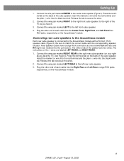
...the tab to the center cube speaker (Figure 5). Connect the wire pair marked LEFT to the Acoustimass module with a 50-foot (15 m) speaker cable (Figure 5). Connecting rear cube speakers to the Acoustimass module Each rear cube speaker is connected to the left front cube speaker. 4. Connect the wire pair marked... _V.pdf • August 13, 2002 Connect the wire pair marked RIGHT to the right front cube speaker (to the right rear cube speaker (on the Acoustimass® module. Rear speaker cables have two wires. Insert the marked (+) wire into the red terminal and the plain (-) wire...
...the tab to the center cube speaker (Figure 5). Connect the wire pair marked LEFT to the Acoustimass module with a 50-foot (15 m) speaker cable (Figure 5). Connecting rear cube speakers to the Acoustimass module Each rear cube speaker is connected to the left front cube speaker. 4. Connect the wire pair marked... _V.pdf • August 13, 2002 Connect the wire pair marked RIGHT to the right front cube speaker (to the right rear cube speaker (on the Acoustimass® module. Rear speaker cables have two wires. Insert the marked (+) wire into the red terminal and the plain (-) wire...
Owner's guide
Page 11
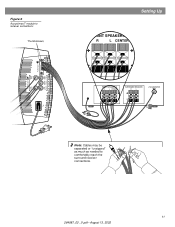
Figure 6 Acoustimass® module to receiver connections Thumbscrews Audio Output Left Rear Right Rear Audio Input Left Center Right Front Front Front Setting Up FRONT SPEAKERS A R L CENTER FRONT SPEAKERS A R L CENTER SURROUND SPEAKERS R L LFE/SUBWOOFER OUT Note: Cables may be separated or "unzipped" as much as needed to comfortably reach the surround receiver connections. 11 264887_00 _V.pdf • August 13, 2002
Figure 6 Acoustimass® module to receiver connections Thumbscrews Audio Output Left Rear Right Rear Audio Input Left Center Right Front Front Front Setting Up FRONT SPEAKERS A R L CENTER FRONT SPEAKERS A R L CENTER SURROUND SPEAKERS R L LFE/SUBWOOFER OUT Note: Cables may be separated or "unzipped" as much as needed to comfortably reach the surround receiver connections. 11 264887_00 _V.pdf • August 13, 2002
Owner's guide
Page 12
...of the powered Acoustimass module into an AC (mains) receptacle. Your Acoustimass speaker system will turn it receives a signal from the module to the cube speakers (Figure 5 and Figure 6). Make sure the cube speakers are connected to your room. Connecting the Acoustimass module to power Note: Bose® recommends ...surround receiver in phase (+ to + and - Setting Up Checking the connections Check all connections from the receiver to the powered Acoustimass® module and from your receiver in and turn on and off automatically as it on all system connections, plug the ...
...of the powered Acoustimass module into an AC (mains) receptacle. Your Acoustimass speaker system will turn it receives a signal from the module to the cube speakers (Figure 5 and Figure 6). Make sure the cube speakers are connected to your room. Connecting the Acoustimass module to power Note: Bose® recommends ...surround receiver in phase (+ to + and - Setting Up Checking the connections Check all connections from the receiver to the powered Acoustimass® module and from your receiver in and turn on and off automatically as it on all system connections, plug the ...
Owner's guide
Page 13
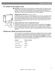
...sounds "thin" or lacks bass, turn the knob in your system For realistic home theater sound CAUTION: The Acoustimass® 6 and Acoustimass 10 speaker systems incorporate an automatic protection circuit, which guards against most kinds of damage from digital surround receivers. If applicable...may be set of low frequency effects on your digital surround sound receiver Your Acoustimass 6 or Acoustimass 10 speakers are compatible with the output from electrical stress or overload. The cube speaker arrays should be exceeding safe levels. However, the following table suggests a set...
...sounds "thin" or lacks bass, turn the knob in your system For realistic home theater sound CAUTION: The Acoustimass® 6 and Acoustimass 10 speaker systems incorporate an automatic protection circuit, which guards against most kinds of damage from digital surround receivers. If applicable...may be set of low frequency effects on your digital surround sound receiver Your Acoustimass 6 or Acoustimass 10 speakers are compatible with the output from electrical stress or overload. The cube speaker arrays should be exceeding safe levels. However, the following table suggests a set...
Owner's guide
Page 14
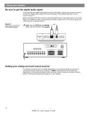
... your surround receiver. DIGITAL PLAY IN IN (OPTICAL) PLAY IN (COAXIAL) DIGITAL PLAY IN IN (OPTICAL) PLAY IN (COAXIAL) FRONT SPEAKERS R L SURROUND SPEAKERS R REAR L CENTER Setting your analog surround sound receiver For analog surround sound (not digital) applications, we recommend that came with your receiver... receiver to WIDE. For additional setup and operating information, please refer to select the digital ouput in the setup menu of each speaker. 14 264887_00 _V.pdf • August 13, 2002 Follow your receiver owner's guide for this process vary, depending on a ...
... your surround receiver. DIGITAL PLAY IN IN (OPTICAL) PLAY IN (COAXIAL) DIGITAL PLAY IN IN (OPTICAL) PLAY IN (COAXIAL) FRONT SPEAKERS R L SURROUND SPEAKERS R REAR L CENTER Setting your analog surround sound receiver For analog surround sound (not digital) applications, we recommend that came with your receiver... receiver to WIDE. For additional setup and operating information, please refer to select the digital ouput in the setup menu of each speaker. 14 264887_00 _V.pdf • August 13, 2002 Follow your receiver owner's guide for this process vary, depending on a ...
Owner's guide
Page 15
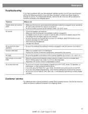
...sure your receiver and player for service. Sound is distorted • Make sure speaker wire is not damaged. • Reduce the volume of the DVD player with your Acoustimass® speaker system, turn off your Bose® dealer to the list of service of fices and phone numbers... enclosed in the shipping carton. to increase bass. No sound • Check the speaker connections. • Make sure that surround...
...sure your receiver and player for service. Sound is distorted • Make sure speaker wire is not damaged. • Reduce the volume of the DVD player with your Acoustimass® speaker system, turn off your Bose® dealer to the list of service of fices and phone numbers... enclosed in the shipping carton. to increase bass. No sound • Check the speaker connections. • Make sure that surround...
Owner's guide
Page 16
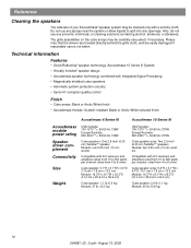
... circuitry • Syncom® computer quality control Finish • Cube arrays: Black or Arctic White finish • Acoustimass module: Scratch-resistant Black or Arctic White textured finish Acoustimass 6 Series III Acoustimass 10 Series III Acoustimass module power rating Speaker driver complement Connectivity Size Weight USA/Canada: 100-127V 50/60 Hz 135W Europe/Australia: 220-240V 50/60...
... circuitry • Syncom® computer quality control Finish • Cube arrays: Black or Arctic White finish • Acoustimass module: Scratch-resistant Black or Arctic White textured finish Acoustimass 6 Series III Acoustimass 10 Series III Acoustimass module power rating Speaker driver complement Connectivity Size Weight USA/Canada: 100-127V 50/60 Hz 135W Europe/Australia: 220-240V 50/60...
Owner's guide
Page 17
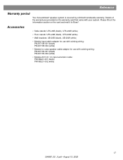
Reference Warranty period Your Acoustimass® speaker system is covered by a limited transferable warranty. Accessories • Table stands: UTS-20B (black), UTS-20W (white) •...8226; Module input cable adapter for use with existing wiring: PN 267138-001 (black) PN 267138-002 (white) • Module-to Bose®. Please fill out the information section on the warranty card that came with existing wiring: PN 267139-001 (black) PN ...; August 13, 2002 Details of the warranty are provided on the card and mail it to -cube speaker cable adapter for use with your system.
Reference Warranty period Your Acoustimass® speaker system is covered by a limited transferable warranty. Accessories • Table stands: UTS-20B (black), UTS-20W (white) •...8226; Module input cable adapter for use with existing wiring: PN 267138-001 (black) PN 267138-002 (white) • Module-to Bose®. Please fill out the information section on the warranty card that came with existing wiring: PN 267139-001 (black) PN ...; August 13, 2002 Details of the warranty are provided on the card and mail it to -cube speaker cable adapter for use with your system.

